In order to create a live action scene with a destruction simulation incorporated I first need to learn how to destroy surfaces and objects in Houdini. The first tutorial I will be using for this purpose is Image-Based Rigid Body Destruction in Houdini on Pluralsight led by Jeff Wolverton which teaches how to destroy a thin surface using a texture image as a starting point. This could potentially be useful as when incorporating live action I could capture an image of the surface I wish to destroy rather than creating a brand new one from scratch.
Scene Set-up
INITIAL OBJECTS
Firstly we need to set up our scene so I created a geometry network containing a wall of approximately 3 metres by 2 meters by 10 centimetres and a sphere primitive with a radius of 50 centimetres, making sure they’re both raised so the bottom of the wall touches the origin and the ball is sat behind the wall. Then lastly I created a new AutoDOPNetwork inside the Geometry Network and connected the wall to input 1 and the sphere to input 2. Also while I’m at this level I created my camera and environment light (set to ambient occlusion) so my shot is already partially set up
RBD OBJECTS
Inside the AutoDOPNetwork drop down to RBD Object nodes and point them at the wall and sphere nodes respectively turning them into rigid objects that obey physics then connect these using a Merge node with the sphere RBD on the left. Below the Merge connect a Rigid Body Solver node via the first input and then set up the rest of the network using a Ground Plane, another Merge and a Gravity node connected to the output. Lastly give the sphere RBD some velocity so when you play the timeline it fires into the wall, I used 17.
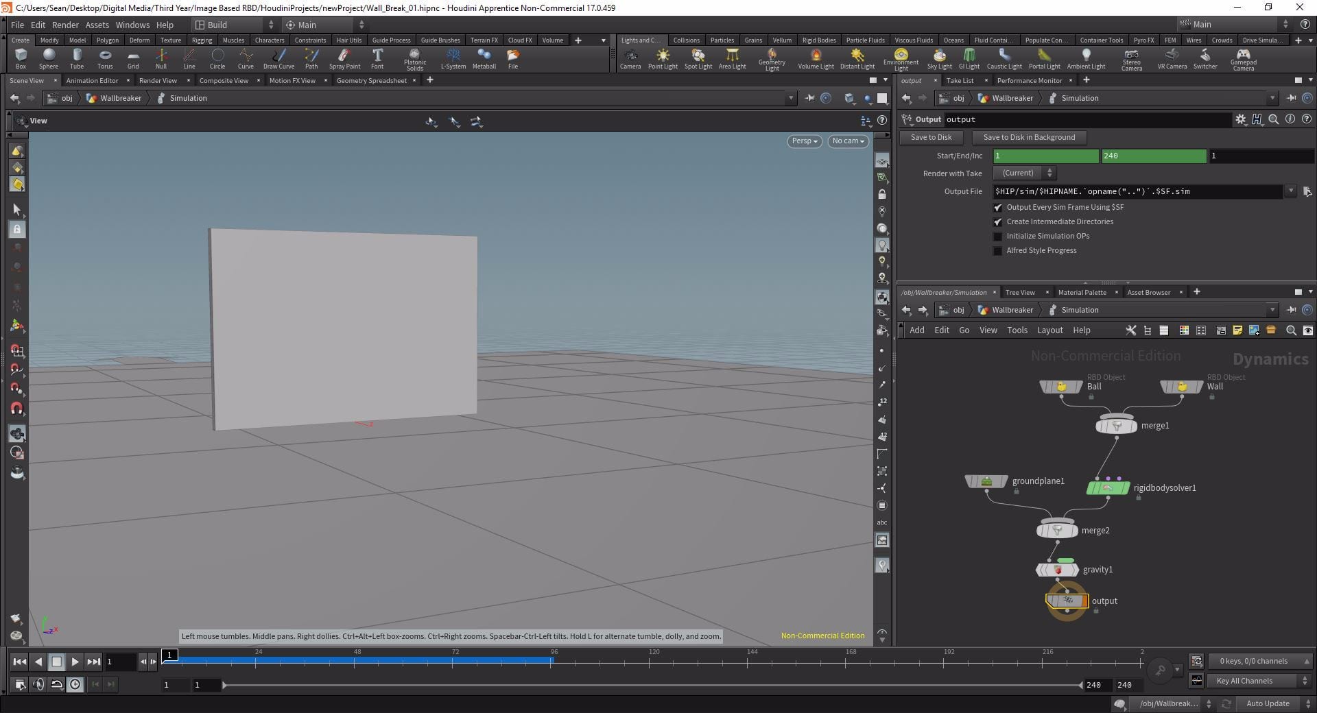
Image set-up
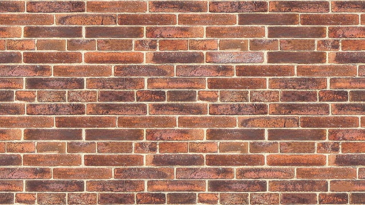
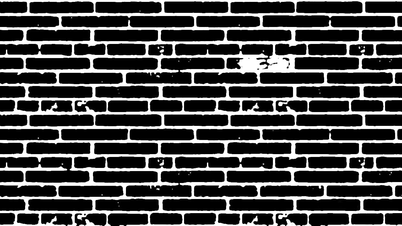
Now I had my scene all set up I had to set up the image so we could break the wall from it. Included in the course files was a brick texture to use, in order to break the wall using it however I needed two images isolating the bricks and mortar. To do this I used the image panel and created an Image Network. Inside the network I imported my brick texture using a File node, connected it to a Null and then to a ROP Output Driver set to export at project resolution to the textures directory to make sure my two images export at the same resolution. Then using a series of colour correction tools, creating a new chain off the original File node, I created an alpha matte isolating the mortar from the bricks and exported both images to my textures folder. While the tutorial series recommends using Houdini’s inbuilt compositor, in future I believe Photoshop would serve the same purpose but with far fewer steps.
Creating the Image Breaker
Setting up the custom network
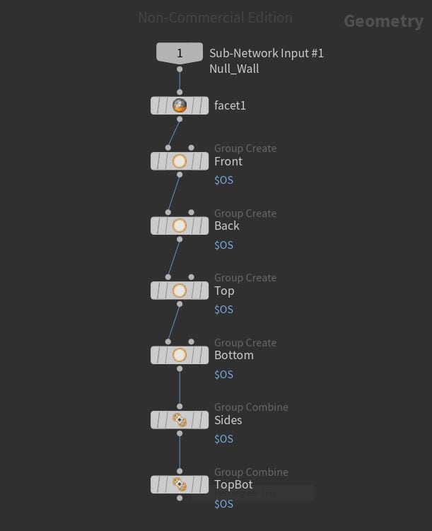
I have my rendered images ready to apply but to actually do this I needed another network. Within the geometry network, between the Box node and AutoDOPNetwork I dropped and Null and then turned it into a Digital Asset using the default settings of 1 input and 1 output – essentially creating a custom node. Within the custom node I added a Facet node to the bottom of the chain with pre-compute normals toggled on so the textures would apply appropriately. I then connected a chain of Group nodes isolating the different faces by their Angle Threshold (in this case 45 as the shape is a cuboid) so that I have a Front, Back, Top, Bottom, Sides, and Top/Bottom group. Finally, I added a custom slider to the Custom Node to control the Angle Threshold for all the group nodes meaning I can now apply this custom node to any shape.
Setting up the Texturiser
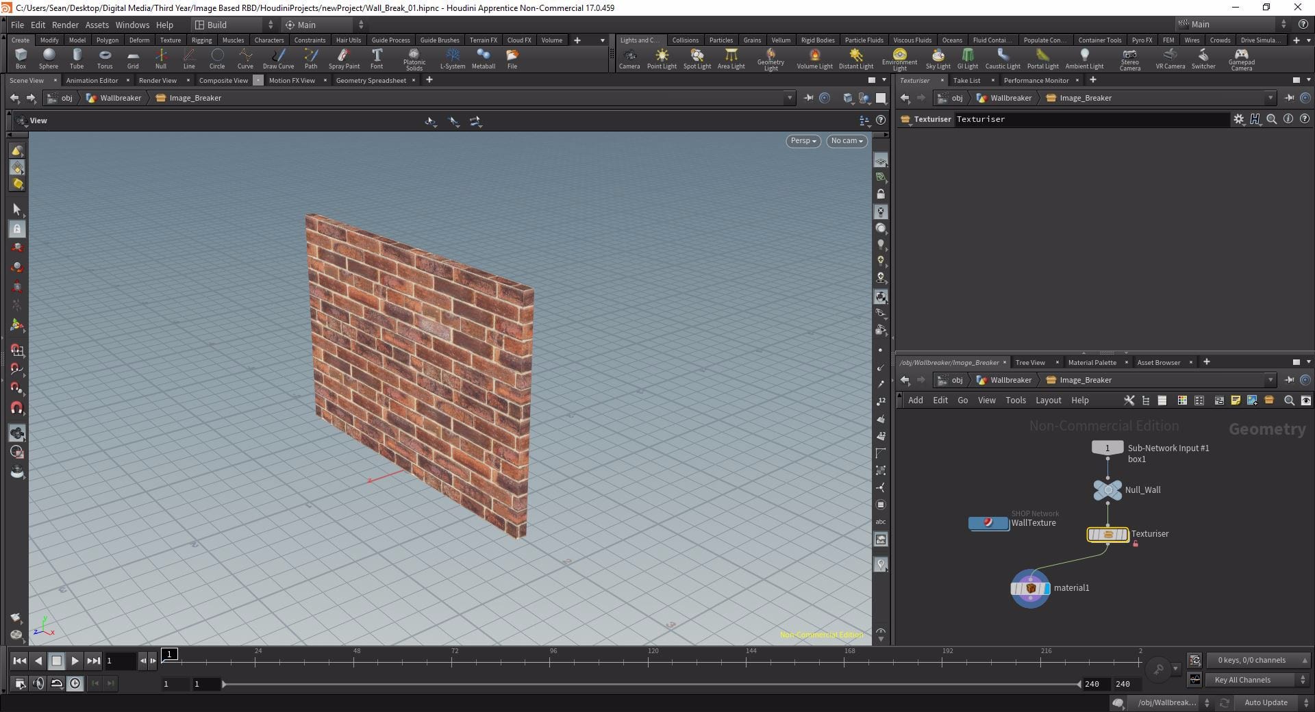
Now I had my groups set up I had to create my second digital asset called the “Texturiser”. I did this via the same method as before but this time highlighting all the nodes in the chain below and including the Facet node and creating a Subnetwork then turning it into a Digital Asset. To actually add textures I dropped down a material node in the chain below the Texturiser and a SHOP Network next to it with a single Decal node beside it. This is where I will add the brick texture I rendered in the previous step but before doing that it was useful to set up another custom parameter for the Image Breaker digital asset so if I want to reuse this network I won’t have to relocate the texture map parameter in the decal node. Now with this parameter link set up I pointed the Texture Map parameter at my brick texture. Lastly, within the Material node I dropped I had to point the Material path at the Decal node – now my materials are linked and ready to be uv mapped.
UV Texturing
To actually get the textures to map I still had to add some more nodes to the Texturiser. At the bottom of the chain I added 3 UV Texture nodes one after the other, each pointed at a different group (1 – Sides, 2 – Top/Bottom, 3 – Front and Back). Each node was set to project only along the corresponding axis and I took the scale on the nodes 1 and 2 down to 0.05 on their respective axis to avoid stretching the textures. It was worth promoting the reduced scale parameters however because it meant I could scale my textures interactively. This was the result:
Creating the Cut Points
The Initial Points
Now my wall had been textured I had to set up the cut points so the wall could actually break apart. To do this I first turned the wall into a volume placing an IsoOffset node after the Texturiser with a Uniform Sampling Division of 100. I then used a Scatter node with a Force Total Count of 100,000 to fill the volume with points then using a Group and a Delete node I deleted any points that were not contained in the wall volume as some were spilling over the sides – fortunately the group node has the option to group by a bounding object, in this case the wall (connected via the 2nd input). Next I added another UV texture node to the bottom of the chain as I needed the UV attribute for the next step and set the Projection Axis to Z so we would only create cut points from front to back.
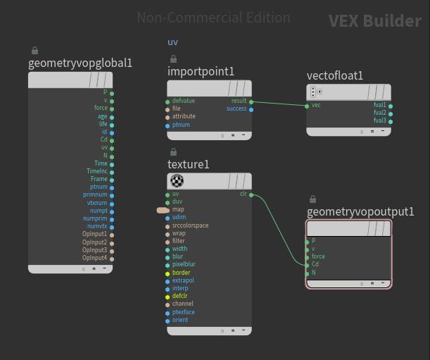
To create the cut points I had to somehow apply my cut map to this volume of points. I did this using an Attribute VOP connected below the UV Texture node. First I imported the UV point data using an Import Point Attribute with the Attribute set to “uv”. I then connected the result of this to a Vector To Float. I also dropped a Texture node in the VOP with the “clr” output connected to the Cd input of the Geometry VOP Output and set the Texture Map to my cut map that I created earlier. What this did essentially was texture the points either black or white based on the cut map I created earlier, now the mortar is white and the bricks are black.
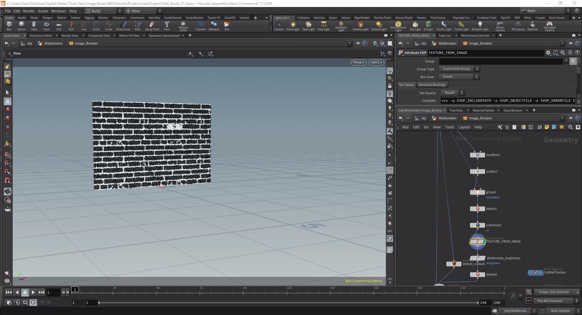
In order to isolate just the white points I had to create an attribute based on the colour values of the points so using an Attribute Create I created the attribute “brightness” creating a custom value using this parameter:
0.299*$CR + 0.587*$CG + 0.114*$CB
Meaning that my points will now have a brightness value based on their colour. Finally, to isolate these, I used a Delete set to Delete Non Selected Points by Expression and used this expression:
if($brightness>ch(“../BrightThreshold”),1,0)
To break this down this means:
- If – creates a conditional expression.
- $brightness – the attribute created in the previous node.
- >ch(“../BrightThreshold”) – is greater than a custom parameter called BrightThreshold that I will set up in a second.
- ,1,0 – Scaled to between 1 and 0.
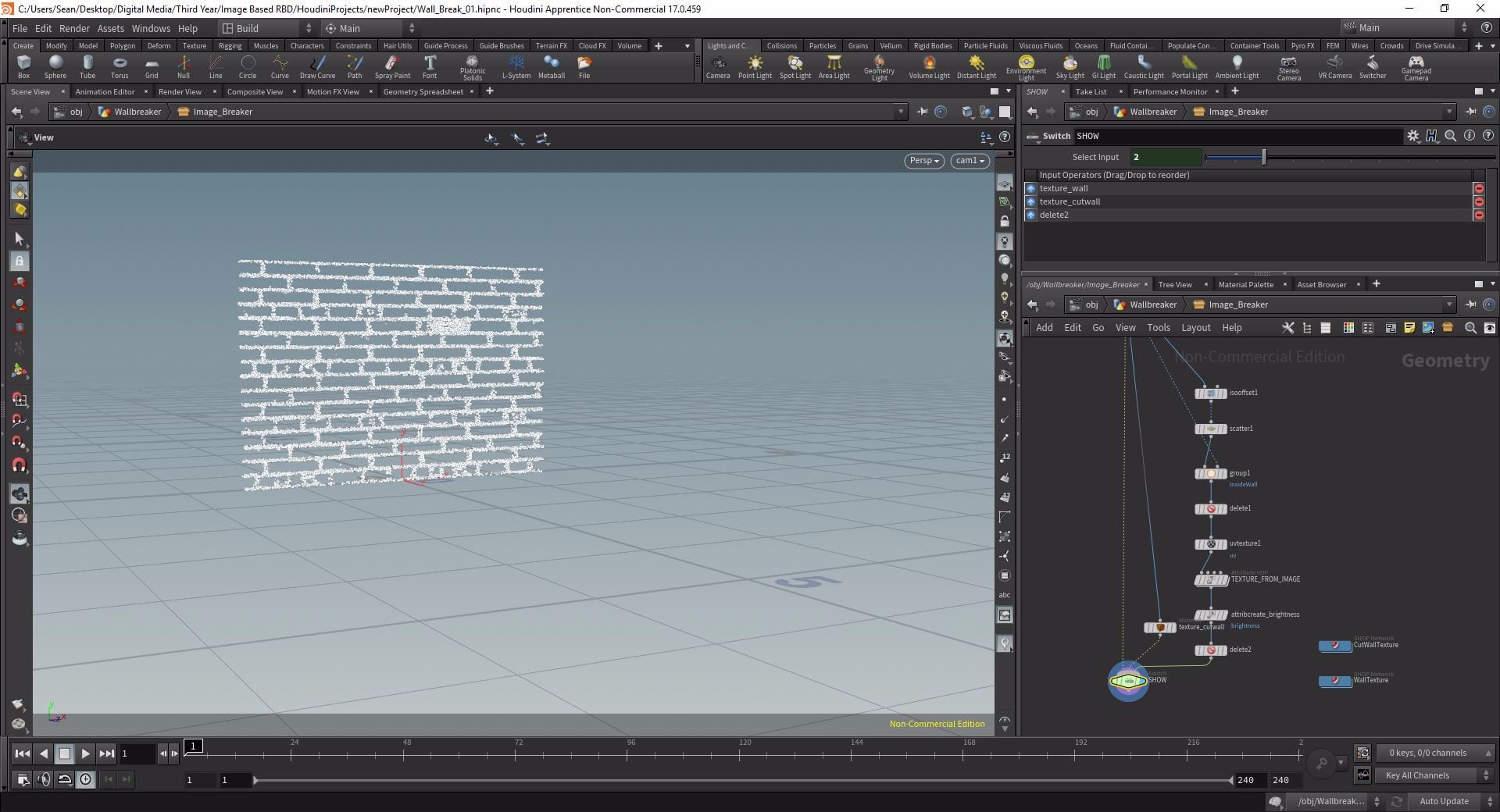
So this node will now isolate points with a higher brightness attribute than that I set as the Bright Threshold. But what is the Bright Threshold? I then created a custom slider for my Image Breaker asset labeled BrightThreshold that just lets me interactively choose a value between 0 and 1 for this threshold. Then I could slide it up and down until all the black points were deleted and only the white ones remained – a value of 0.21 seemed to work best.
Improving the cuts POINTS
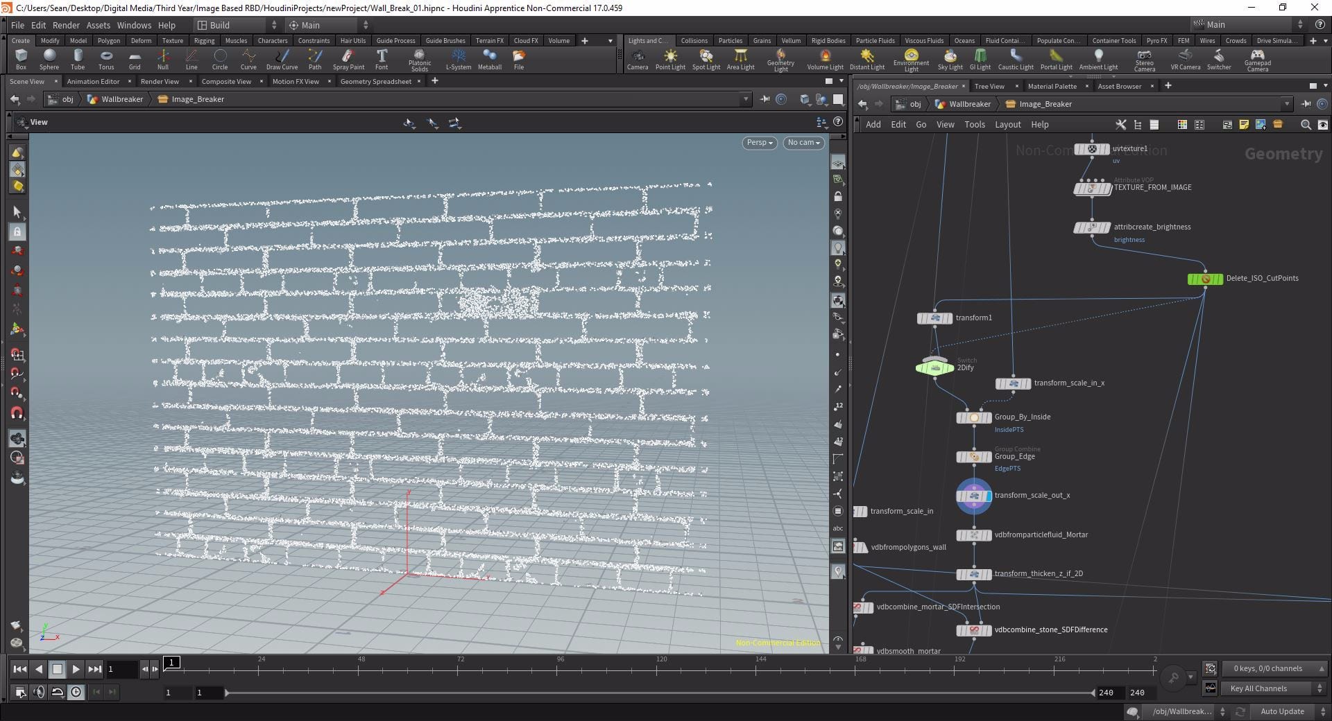
I have my cut points but they aren’t quite ready to be applied yet. Firstly I made them 2D using a transform set to scale the z axis to 0. However the points still only just reached the edges of my wall meaning the edge bricks may not necessarily be separated. To fix this I scaled my wall in slightly in x, creating a separate chain from my wall import, then using a Group node with my cut points in the left input and scaled in wall in the right I created 2 groups of points using the slightly scaled in wall as a bounding box called “insidepts” and “edgepts”. The edge points only contained this points that were right on the edge so to make sure they would cut all the way out I simply scaled them back out in x so they spilled over the side of the wall geometry.
Creating the VDBs
The MORTAR VDB Setup
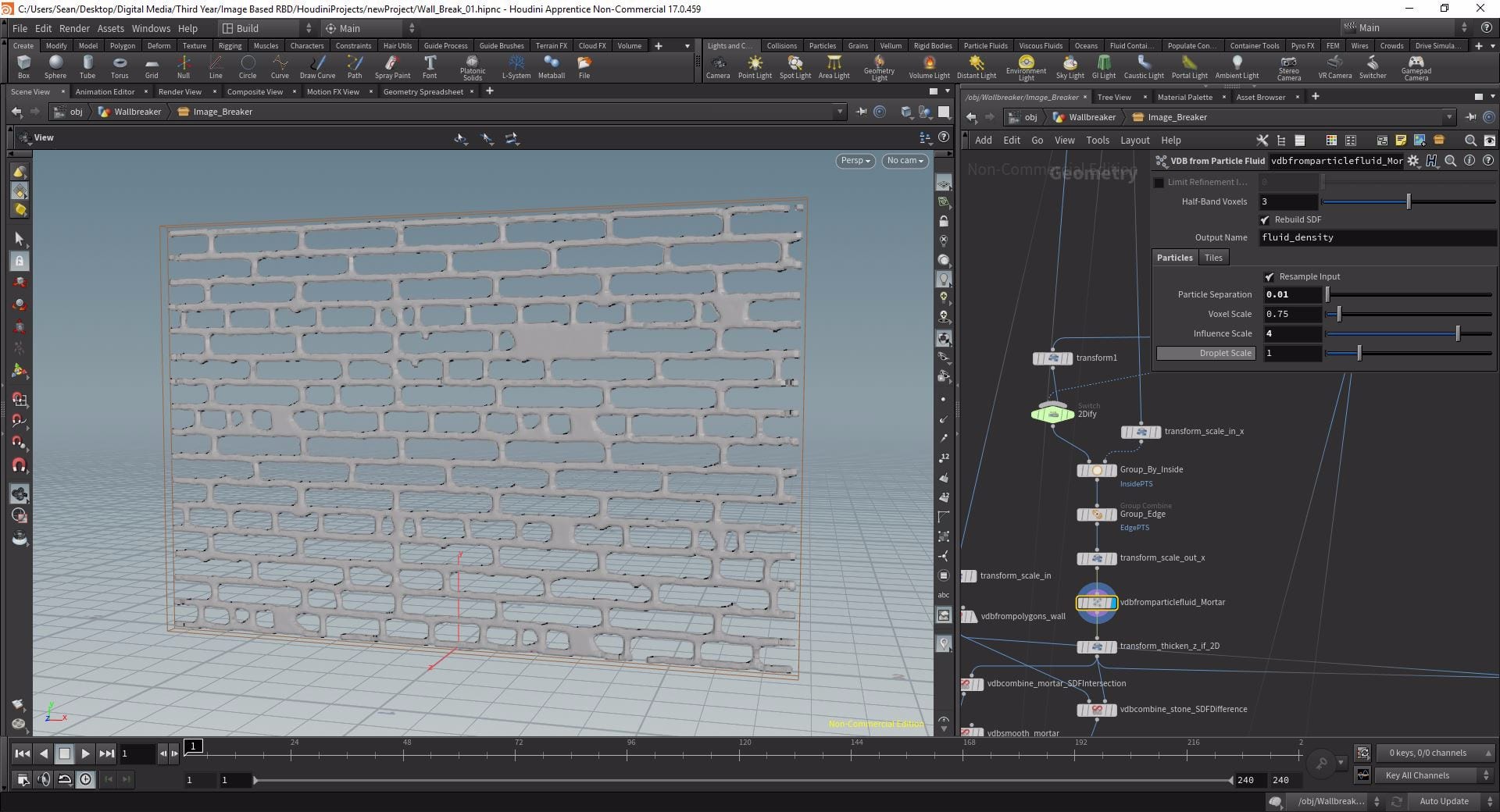
Now I had my points I had to turn it into geometry in order to apply it to my wall, to do this I turned it into a VDB. A VDB or “Voxel Data Base” is a quick way of storing voxel geometry data and there are various nodes in Houdini used to build them from different states. For this process the VBDFromParticleFluid was the most appropriate, even though we are not working with fluids in this simulation this node is a great way of generating a VDB from points. At first the VDB was just one big lump of geometry but, by lowering the particle separation, I was able to make geometry only be generated in the mortar areas – by increasing the Influence Scale from 3 to 4 this effect was amplified.
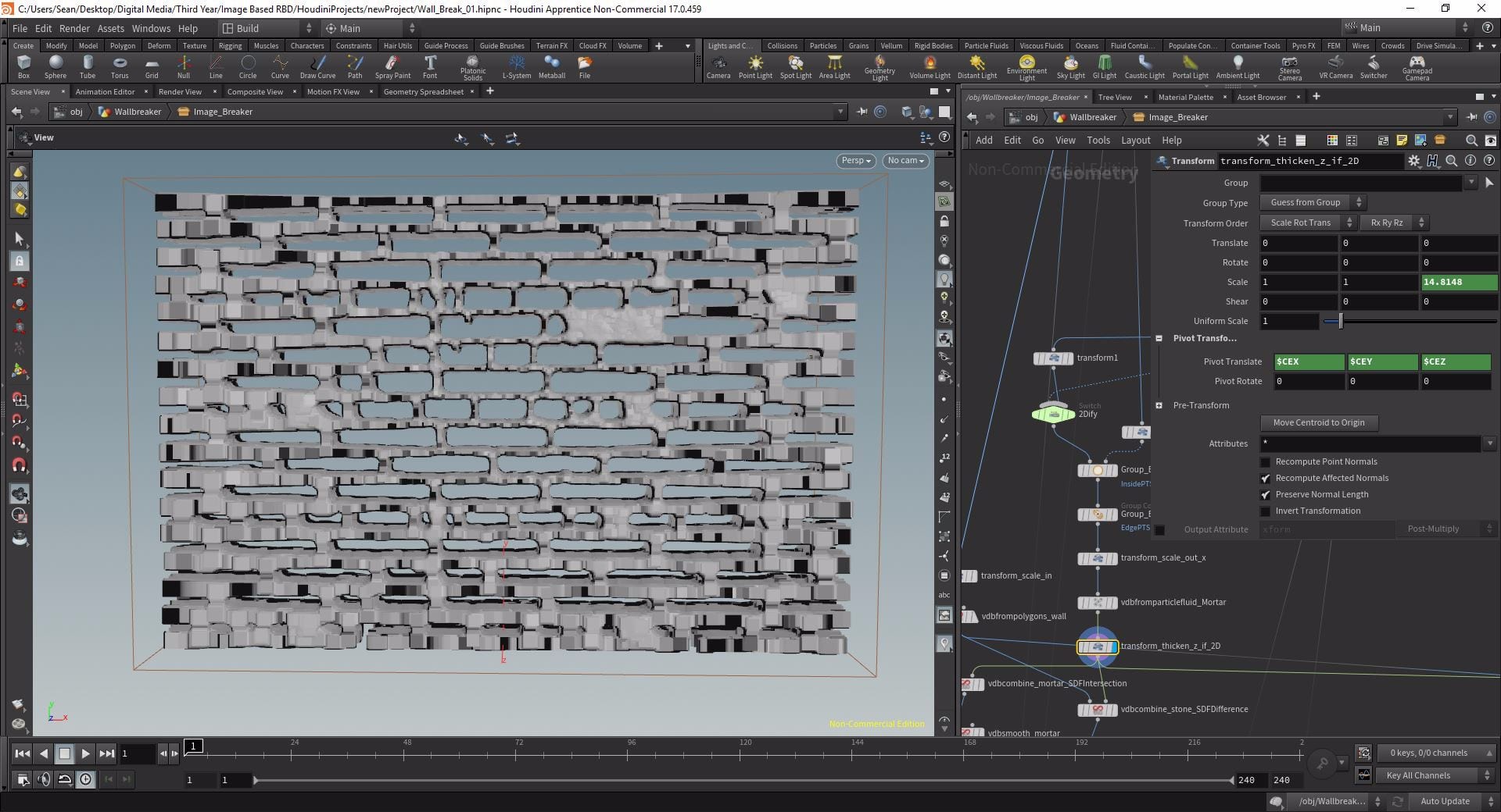
Now I had my mortar VBD but it needed to be thicker as I had scaled it down earlier. To scale it back up I used another Transform with this parameter in the z-scale:
10*bbox(“../WALL”, D_ZSIZE)/bbox(“../VDB”, D_SIZE)
What this is doing is taking the thickness of the original wall (bbox(“../WALL”, D_ZSIZE)), dividing it by the thickness of the VDB (bbox(“../VDB”, D_SIZE)) and then multiplying that result by 10. This value is then used as the value by which to scale the thickness meaning it will always be thick enough I was to use this network for a different texture.
The mortar and the stones
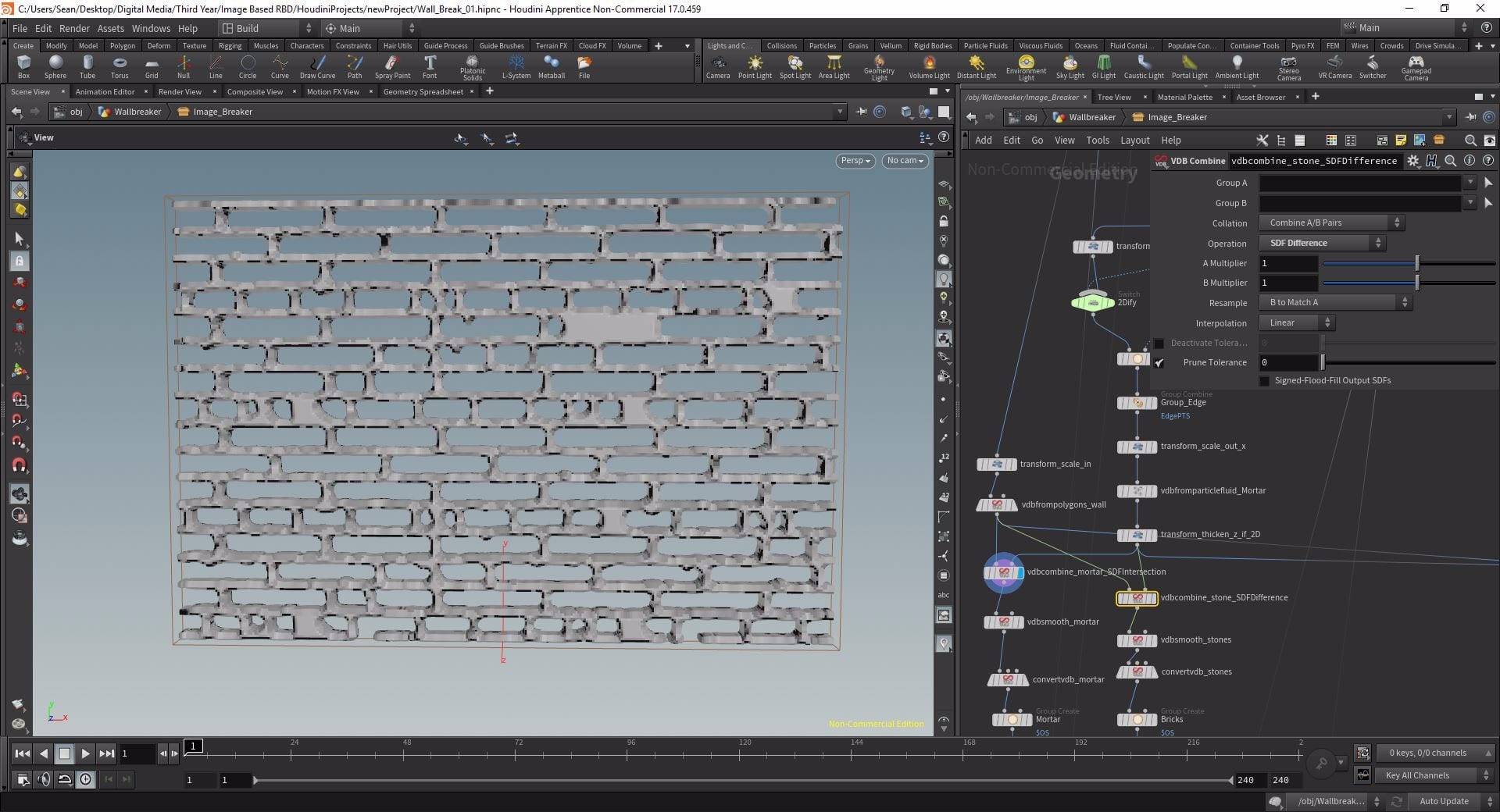
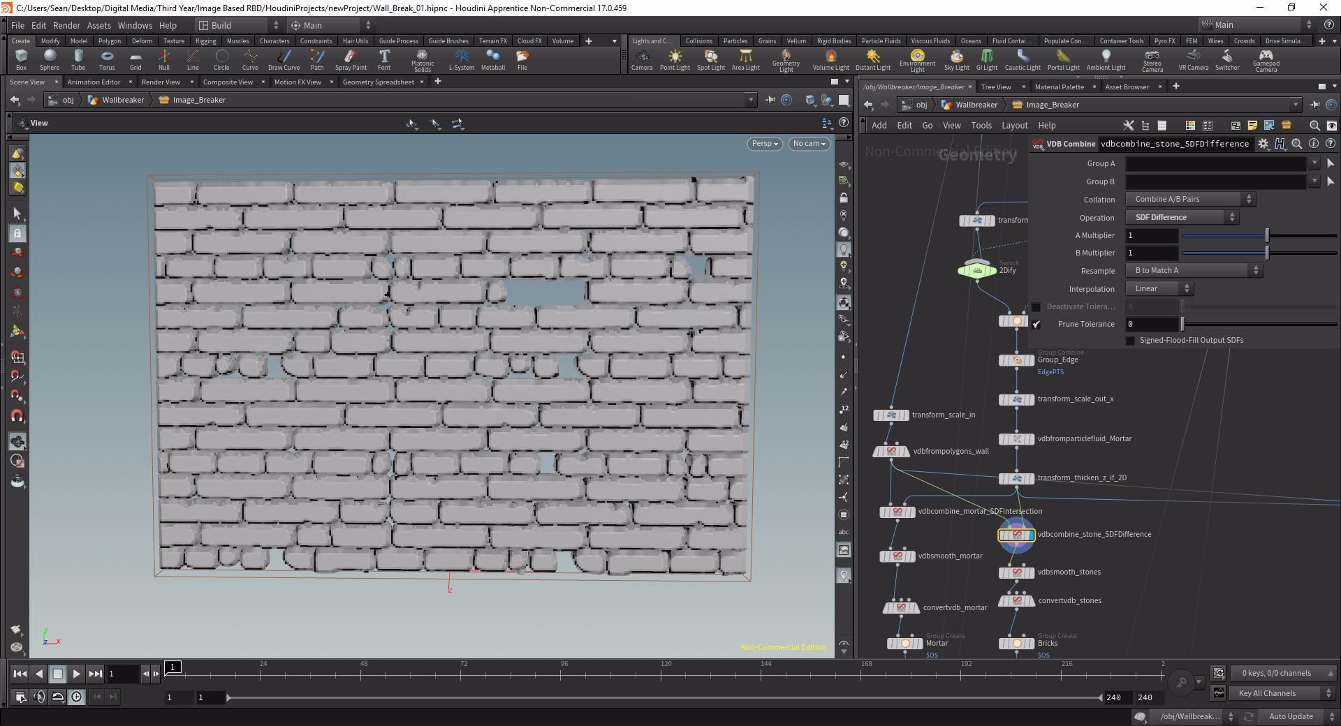
Time for me to actually create the VDBs that will generate our polygons, to do this I used two VDB Combines. In the left inputs I plugged a new chain from the Wall import containing a Transform that scaled down the uniform scale to 0.999 and a VDB From Polygons with a Voxel Size linked to the Particle Separation of the VDB From Particle Fluids. Into the right inputs I plugged the mortar VDB I already created. For one of the combines I set the operation to SDF Intersection and the other to SDF Difference, the intersection created the final Mortar VDB and the difference the Bricks.
TUrning the VDBs into Polygons
Using a Convert VDB under the Intersection VDB Combine I converted my mortar VDB to polygons with an Adaptivity of 0.2. Now instead of just a rough representation of geometry for my mortar I had a set of tiny polygons that ready to be broken apart in DOPs.
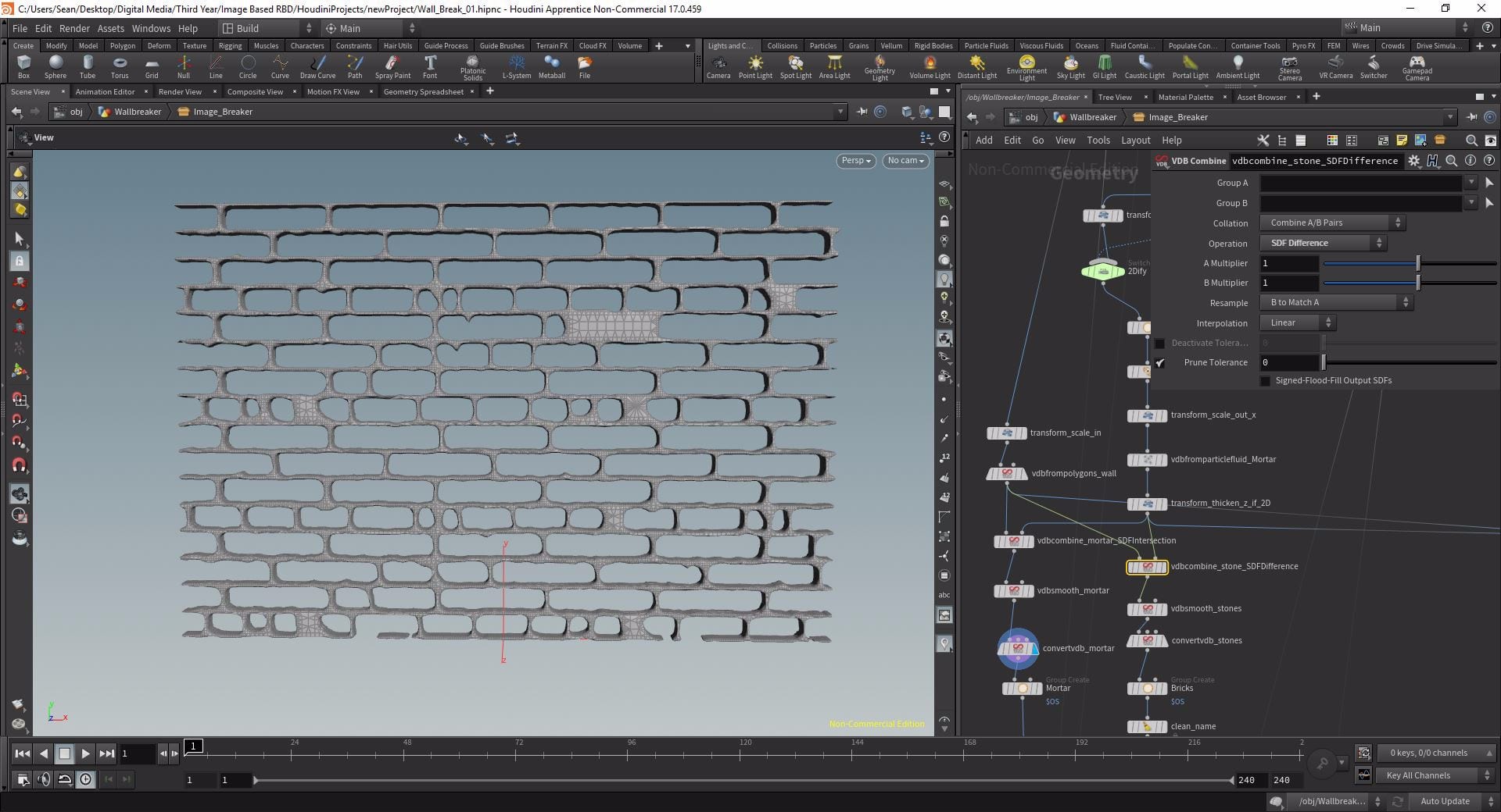
I duplicated this Convert VDB and connected it to the Difference VDB Combine, applying the same operation to the bricks VDB however these would need some refinement. The first step was dropping a VDB Smooth above the Convert with 0 Iterations as the bricks looked a little lumpy, I then copied this over to the same position in the mortar chain and placed group nodes at the end of both chains so I had a set group for my unbroken mortar and for my bricks.
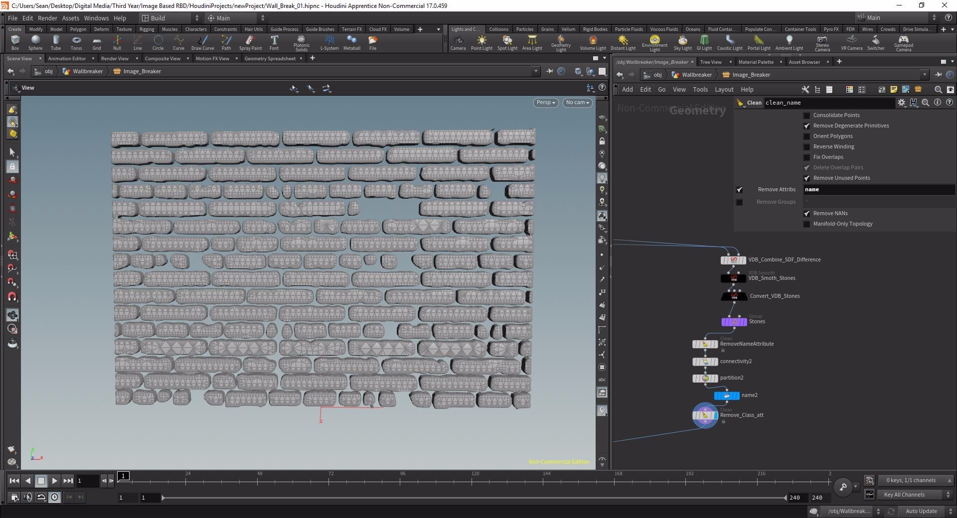
Improving the Bricks
Using a Clean node I removed the name attribute from the bricks and then used a Connectivity node to assign each brick a “class” value based on whether it was connected to another polygon or not, before finally using Partition node with a rule of “Brick_$Class” to effectively isolate each individual brick into their own “Primitive Groups”. Then I reapplied the name attribute with a Name node set to “Name From Group” and with a Group Mask of “Brick_*”. Lastly I used another Clean node just to get rid of the class attribute as I didn’t need it anymore.
Unfortunately, in Houdini 17, due to updates in some of these nodes this part of the chain does not function as it should anymore. When I reached the simulation phase my mortar was breaking up as it should but the bricks had not been partitioned properly and so appeared to have invisible bonds between them holding them together. I do not know exactly how to fix this with the new versions of the nodes but copying over the Connectivity, Partition and Name nodes from the Pluralsight exercise file fixed the problem for me.
Cleaning up and Texturing
I then merged my unbroken mortar with the named and classless bricks to bring my wall back together then used a Fuse node to delete some unnecessary points and fill any open spaces that needed filling. I made sure my wall had the correct normals using a Normal node and then dropped another Texturiser at the end of the chain with parameters linked to the first and copy/pasted my wall texture Material node below it. Now I had my two groups of geometry, the mortar and the bricks, but merged together and textured.
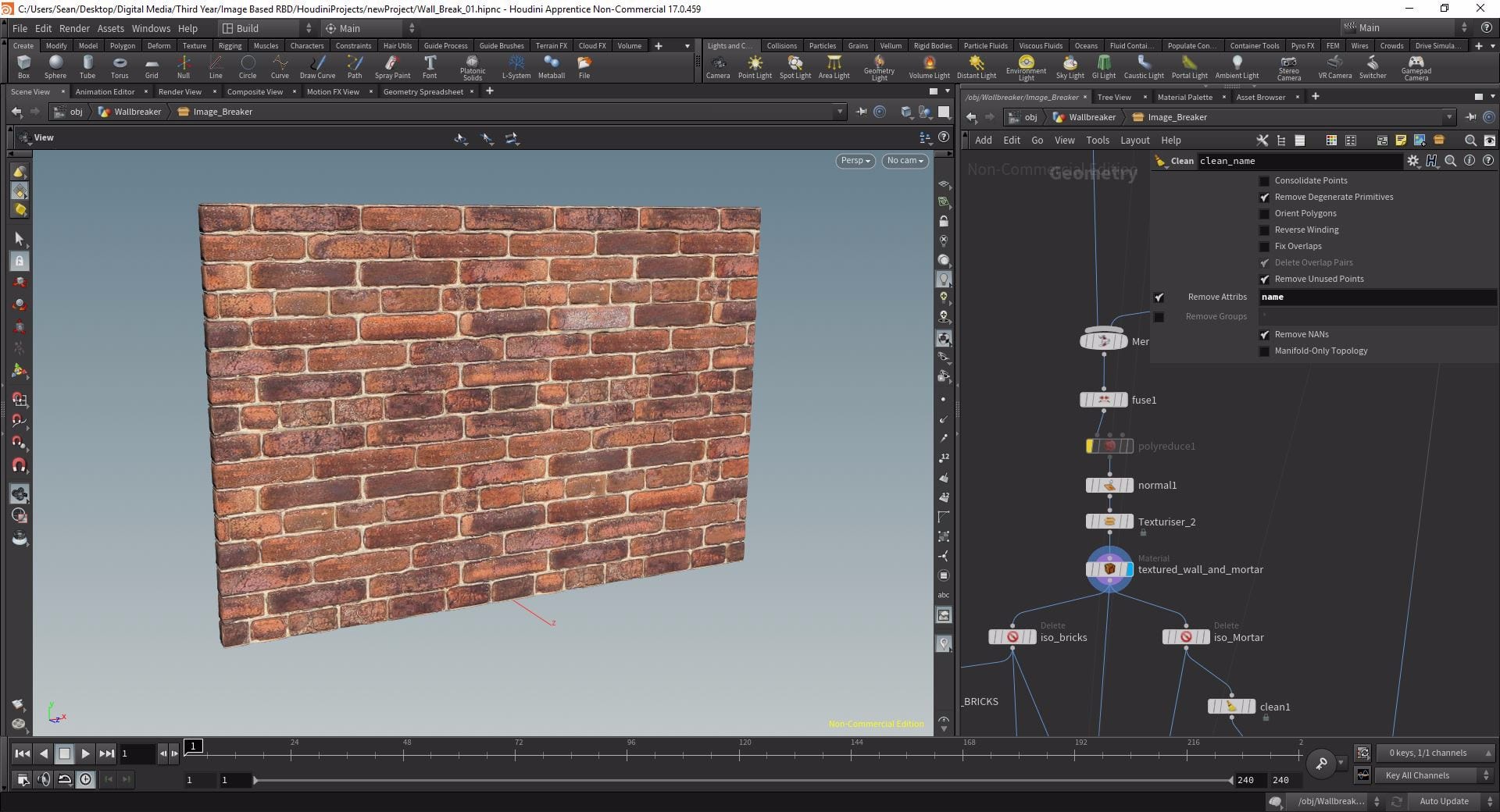
Now if I dropped down two Delete nodes and isolated the bricks and the unbroken mortar back out using the groups I created earlier they were both textured not only on their visible faces, but also on those inside the wall.
Breaking up the mortar
Determining the Cut Points
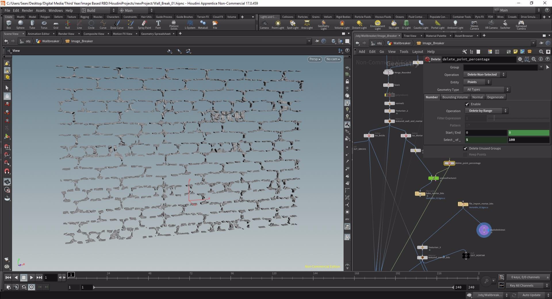
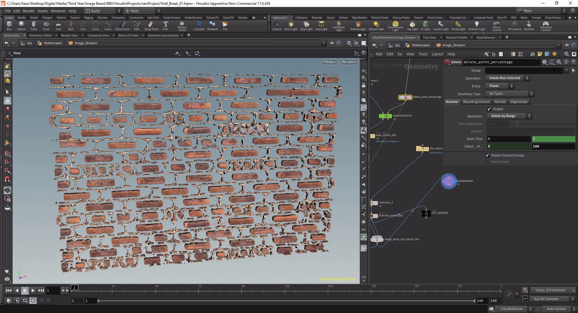
At this point I have my isolated bricks and unbroken mortar (both textured) and I have the cut points I generated earlier with the alpha matte, it is time to actually cut up the mortar so it can be blown apart in DOPs. To actually do this though I didn’t use all the cut points I’d generated as the mortar bits would be ridiculously small and take forever to sim – instead I just used a percentage.
Below the Delete node that isolated my cut points I dropped another Delete node, creating a new chain, set to delete non-selected points by range. In the “Select_of_” parameter I changed the second value to 100 (as in 100% being the maximum) and linked the first value to a custom slider that I created that outputs a value between one and 100. This meant I could interactively change how many points would be used to cut, using the slider I could pick the percentage of points out of 100 that I wanted to use – I settled on 5%.

Applying Voronoi
For this use of fracturing I used Houdini’s Voronoi fracture node as the pieces being broken up will be so small it doesn’t matter if the breakup looks linear. First I used another default Clean node to get rid of the attributes on my isolated, textured, unbroken mortar so they didn’t interfere with Voronoi. Then into the first input of the Voronoi Fracture node I plugged the Clean and into the second input, the cut points. The only parameter I changed within this node is the Name Prefix which I changed to “mortarpiece”. Other than that I simply let the node do it’s task and cut up the mortar, this took some time so afterward I cached a single frame and re-imported the data using a File node.
Re-texturing
By using the Clean node before the Voronoi Fracture I wiped the textures from my unbroken mortar so now I have my mortar pieces I had to re texture them again. This was very simple luckily, I just duplicated the Texturiser and Material node from before and connected them to the bottom of the File node.
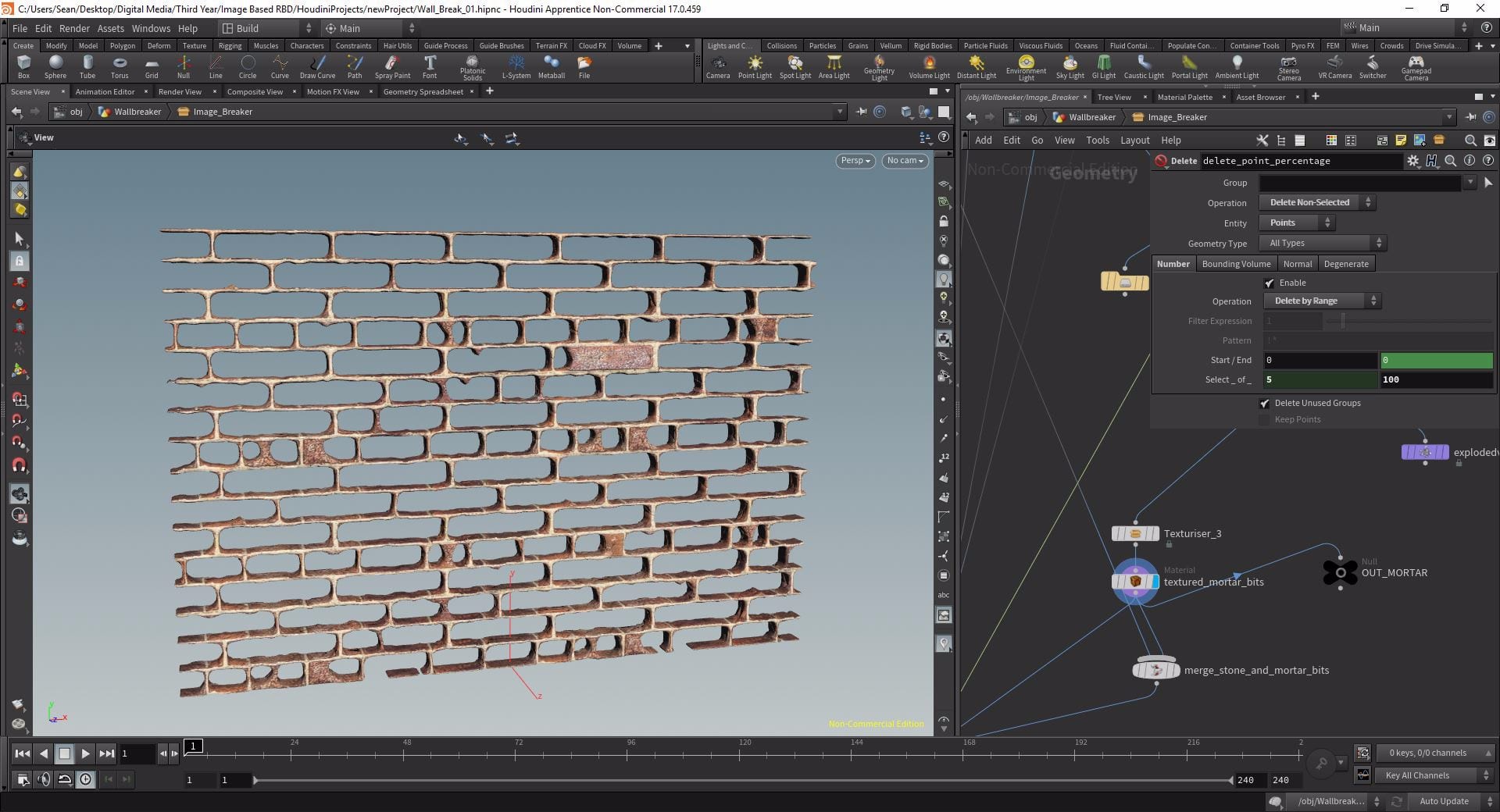
Finally I used another Merge to combine my textured bricks with the textured mortar bits with a Null beneath this named OUTPUT. I finally had my bricks textured on all sides and my broken up bits of mortar, again textured on all sides and ready to be broken up in DOPs.
Simulation
My simulation phase took a very long time and there was an extensive amount of trial and error involved for what is actually quite a simple simulation. The main reason for this was the physical properties of the wall which I will cover in this section.
Scene Set Up
I already had my AutoDOPNetwork that I created earlier but I created a new one from scratch, I also made sure there were 3 balls instead of 1 of smaller size and staggered them so they would all hit the wall one after the other for a more interesting effect. My DOP network once I had set it up consisted of 3 RBD objects with physical properties and velocities all linked together bringing in the 3 balls respectively. These were merged with an RBD Fractured Object node pointed at the OUTPUT null so my wall was brought into the scene. The Merge was then connected to the first input of an unmodified RBD solver to calculate the collisions. I needed a ground plane as well so merged this in below the solver, below this was my Gravity Force node and then the Output.
Simulating
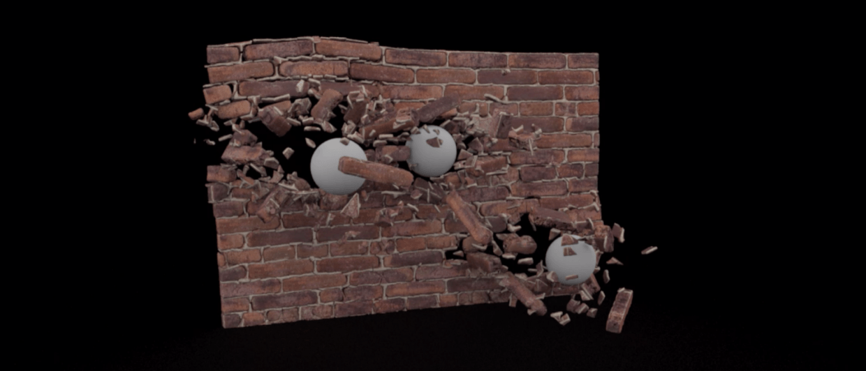
I gave the balls an initial velocity of 17 and flipbooked a few seconds of the simulation, this was the result.
On the plus side the simulation worked! The bricks and mortar bits were separated appropriately and the whole thing collapsed. However the bricks and mortar are bouncing around like they’re made of polystyrene. I therefore went back and edited the physical properties of the wall giving it a much higher density and reduced the bounce to practically nothing.
This simulation was much better, as you can see the bricks lose their velocity much quicker once they hit the floor and the balls themselves slow down because of the increased density.
After a few more tweaks I settled on the values used in this flipbook. The wall had a density of 3000 a bounce of next to nothing and a much higher friction to account for the roughness of the material, I also increased the density of the balls somewhat so they would break through the wall better. Here is the rendered result.
For a while I was satisfied with it, the textures looked good and the bricks seemed to be falling appropriately. However the mortar bits did not seem to be behaving properly, the just kept on rolling around on the floor, not losing their velocity as the simulation went on.
I therefore went back to the DOP Network and continued playing with the physical properties. In the end I used two RBD Fractured Object nodes, 1 brining in the bricks and 1 the mortar bits. I then looked up the actual real world values for the density of a brick and calculate what that should then be for a wall of this size. I increased the density of the mortar bits as well relative to this and significantly reduced the bounce and increased the friction of the ground plane. While all this helped create a more realistic simulation, the mortar bits were still skittering around the floor long after they should have come to rest. In the end I solved the problem using two techniques i found on a forum. I changed their collision geometry from a convex hull (essentially a rounded representation of the geometry that was causing the bits to roll) to a box meaning it was harder for the bits to keep their velocity. I also used a RBD Auto Freeze node to essentially tank an objects velocity when it reaches a certain threshold, forcing the bits to slow down and freeze once they became slow enough. The result still isn’t 100% perfect, however it did solve the problem with the mortar bits rolling along the floor.
Final Thoughts
I am very happy with the final output of this method of fracturing, by using real world values for the physical properties of my simulation the simulation looks very realistic and if integrated in live action would likely not look out of place or computer generated. However the technique is somewhat outdated. I’m sure there is a work around for the Partition – Connectivity – Name stage that could be easily implemented, but I do not have the sufficient knowledge of the program and all it’s various nodes and properties to find that. Therefore, if possible I will use a different method of fracturing for the live action section of the output of this project.
References
- Pluralsight (2015) Image-based Rigid Body Destruction in Houdini. Available from: https://app.pluralsight.com/library/courses/rigid-body-destruction-houdini-2169/ [accessed 19th February 2019].
- Forum post regarding bringing debris to a stand still: https://forums.odforce.net/topic/19627-bring-rbd-objects-to-complete-stand-still/ [accessed 19th February 2019].