
One of the limitations of Voronoi fracturing, as discussed in an earlier post, is that the fractured pieces are not detailed at all. On the fractured piece’s exterior this is not a problem as this geometry doesn’t change, but on the piece’s interior (the section that could not be seen prefecture as it was attached to the adjacent piece) should not usually also be flat. However the Voronoi Fracture node does not account for this leading to very uniform fractured pieces. Luckily there is a workflow you can apply post-simulation in order to “UpRes” the fractured pieces. The added benefit of adding detail at this stage is it does not increase sim time as you have already simulated and cached your RBD sim.
Increasing PiEce Resolution
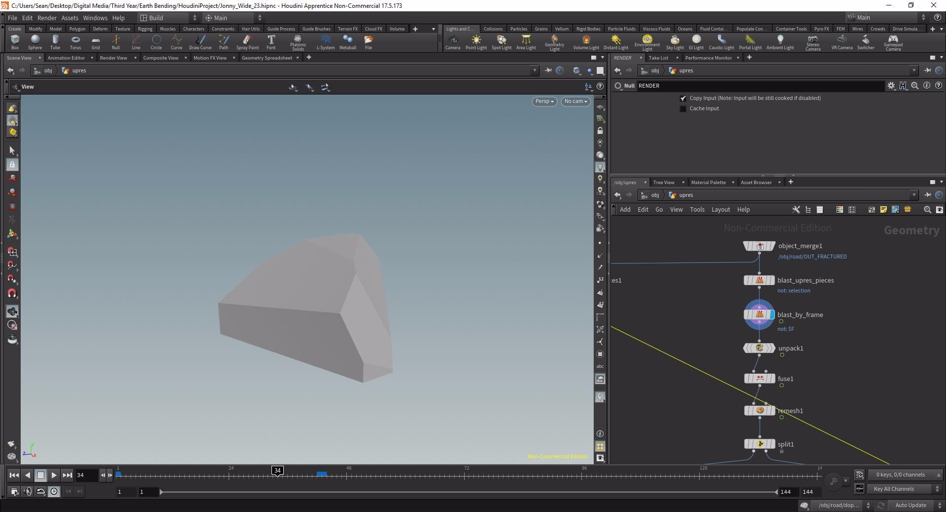
Isolating pieces by frame
The first step in UpRes-ing the pieces is actually increasing the resolution of each individual piece by subdividing it a number of times, in Houdini this process is called re-meshing. To do this, first bring in the fractured pieces into a new Geometry network with an Object Merge, then isolate a single piece per frame using a blast node set to Delete Non Selected with a group of $F. This means that on every frame only the corresponding piece will be shown. The benefit of such a workflow is that later we can instance our pieces rather than doing them all at once which, in simulation with a large number of fractured pieces, is quite intensive on the computer.
Re-meshing the piece
In order to edit the piece attach an Unpack node to the end of the chain and a Fuse below that to remove any unnecessary or duplicate bits of geometry. Below the Fuse drop a Remesh in order to add resolution to the piece. The Remesh node is quite intensive so reduce the Target Edge Length the 0.003 and set the Hard Edges Group to Outside. The piece has now had its resolution increased significantly and each face is made up of thousands of tiny polygons.

Setting up the inside and the outside
At the moment all sides of the piece will have been re-meshed equally but this may not be your desired effect. As mentioned before, in a fracture it is generally only the interior faces that need UpRes-ing as the exterior faces shouldn’t have changed from their initial state. In order to apply this to the pieces in Houdini drop a Split node below the Remesh with the Group set to outside. The inside and outside groups were created by the Voronoi Fracture node and tell Houdini which faces are interior faces and which are exterior. If you display the Split node you will see that the exterior pieces have been isolated and the interior ones deleted. Invert the selection and then connect a Null to each output now the outside group has been isolated from the inside group.
Down-Resing the Outside
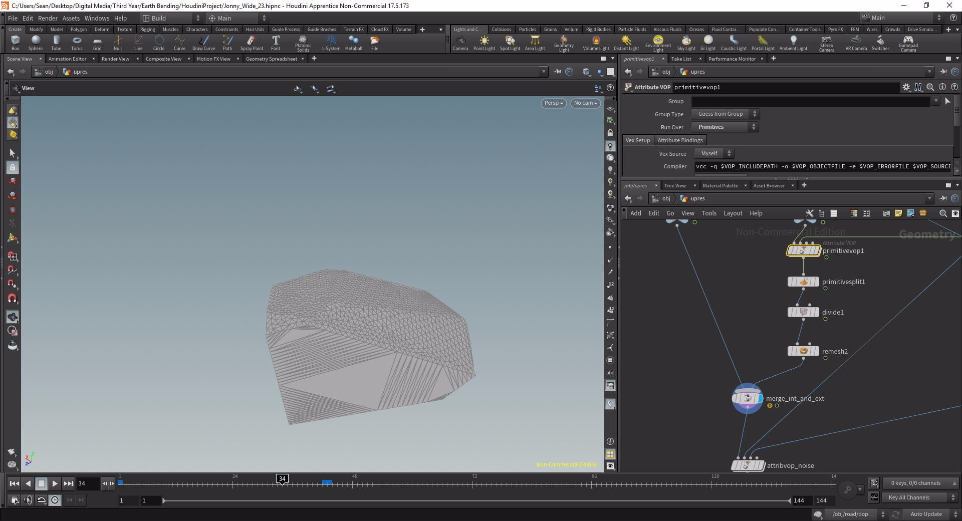
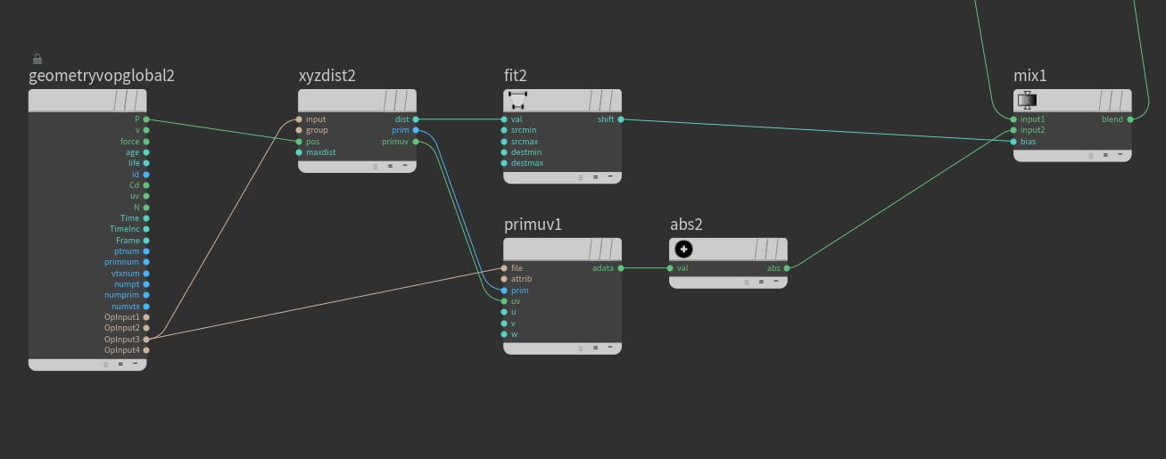
All the extra resolution on the outside faces is unnecessary so the next step is to down-res them again so the calculation time is not necessarily large. To do this put a Divide node at the bottom of the outside faces branch with Maximum Edges and Triangulate Non-Planar disabled but Remove Shared Edges Enabled. At the moment this will destroy the piece because it cannot differentiate one face from another. To fix this drop an Attribute VOP above the Divide set to Run Over Primitives. Into the second input of this VOP plug in the original un-fractured geometry via an Object Merge then jump into the VOP layer.
Using this VOP with the original geometry plugged in the original faces of the geometry can be preserved allowing the Divide to work properly. First drop down an XYZ Distance VOP with Output 2 plugged into the Input and P plugged into Pos. From this distance an attribute can be created using a Bind Export connected to the Prim output of the XYZ Distance. This will export the index to the closest primitive and output it as an attribute which we will call splitId using the Name field. Back up at SOP level drop a Primitive Split below the Attribute VOP and set the Attribute to splitId. Now when the Divide has the view flag the piece’s outside faces are split into 3 or 4 primitives each. Re-mesh this once more using the Remesh node with a Target Edge Length of 0.01 and Use Input Points Only enabled so now there are about 4,000 primitives per piece instead of 80,000. Lastly using a Merge rebuild the piece by plugging isolated inside pieces with the less dense outside pieces.
Adding interior Noise
Setting Up The Noise
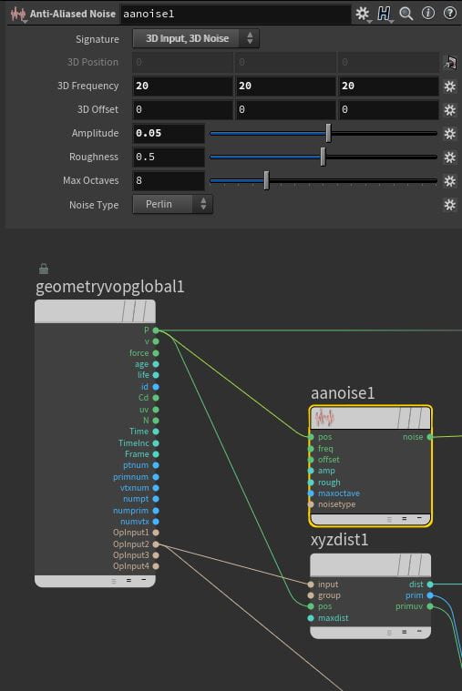
Now both the interior and exterior of our piece is at an appropriate resolution the next step is to add noise to the interior faces so the pieces do not look like they have been cut apart with precision. To do this drop another Attribute VOP after the Merge and inside it place an Anti-Aliased Noise with the pos input connected to P. Change the Signature to 3D Input, 3D Noise and then place an Add VOP with P and the Noise plugged into Inputs 1 & 2. Plug the Sum of this into the P output to apply the noise to the piece and you can see it warping the piece significantly.
Masking the Noise
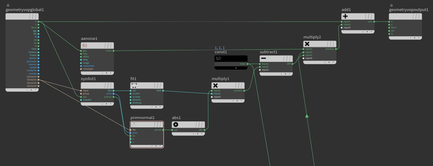
Currently the noise is effecting every face including the flat sides whereas we just want it to effect the interior pieces, to fix this we will create a mask. Back at SOPs plug the original geometry into the second input of the Attribute VOP then head back into VOPS. Drop another XYZ Distance with the same input paths as before but this time output the Distance into the Value input of a Fit Range. Invert the range by swapping the Destination Min and Max and set the Source Max to 0.1 then output the Shift into the Cd of the Geometry VOP Output. This will colour the interior sections black and keep the exterior white, if this is the case then the XYZ Distance has worked effectively and the process can be continued so disconnect the Shift from the Cd.
To apply this mask to the noise drop a Primitive Normal with the Prim and UV input connected to the corresponding outputs of the XYZ Distance and File connected to Opinput 2. We need all the numbers to be positive so connect the output of the Primitive Normal to an Absolute and then Multiply it by the Shift of the Fit making sure the Absolute is in the top input so a vector is being output. Next drop a Constant set to output the Vector 1, 1, 1 and subtract it from the multiplied value by plugging the Constant into the 1st input of a Subtract VOP and the Multiply into the 2nd. We will use this value to scale down the noise so drop another Multiply with the Noise plugged into Input 1, the Subtract into Input 2 and the output plugged into the second input of the Add created earlier.
The noise itself needs to be reduced significantly so, in the Anti Aliased Noise, reduce the Amplitude to 0.05 and set the 3D Frequency to about 20 across the board.
Maintaining the Outside Edges
Our instanced piece is nearly complete however, if you have multiple pieces of geometry, the corners between them will not have been preserved. To fix this, connect a Convert Line to the bottom of the Object Merge bringing in the original geometry forming a separate branch. This creates a wireframe version of the geometry preserving the original edges, connect a Facet and enable unique points then a Poly Frame. We only need the tangentu attribute so disable the Normal Name and then plug it into the third input of the Attribute VOP.
Back inside VOPs duplicate the XYZ Distance and the Fit Range but change the file connection from Opinput 2 to 3 to bring in the edges. Then drop down a Primitive Attribute with Opinput 3 plugged into file and the prim and primuv outputs of the XYZ distance plugged into their corresponding inputs. Change the Attribute from Cd to tangentu and then plug it into an Absolute to keep all the numbers positive then we need to mix in this value. Drop down a Mix VOP with the Constant from earlier plugged into Input 1, the Absolute into Input 2, and the Fit Range into the Bias, then make the Mix Input 3 on the final Multiply. Now if there will be no noise created on exterior edges for example in a wall where a window would go.
Cleaning up the pieces
Before we export the UpResed pieces drop down two Normal SOPs one after the other below the Attribute VOP. Set the Cusp Angle of the first to 0 and then the second to 90 but only apply it to the Inside group. We also need to clean up the groups so add a Group Delete to the bottom of the chain with the Groups set to *.
Rebuilding the geometry
Bringing in instanced pieces
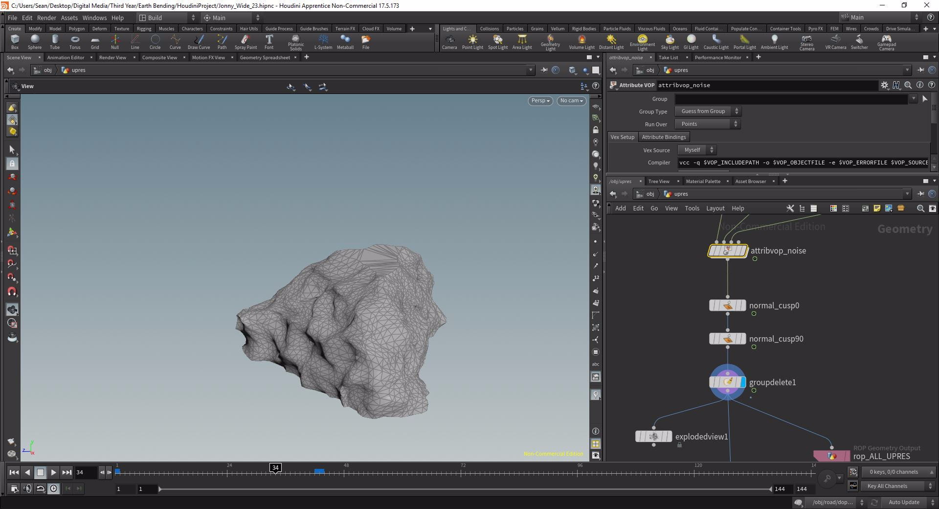
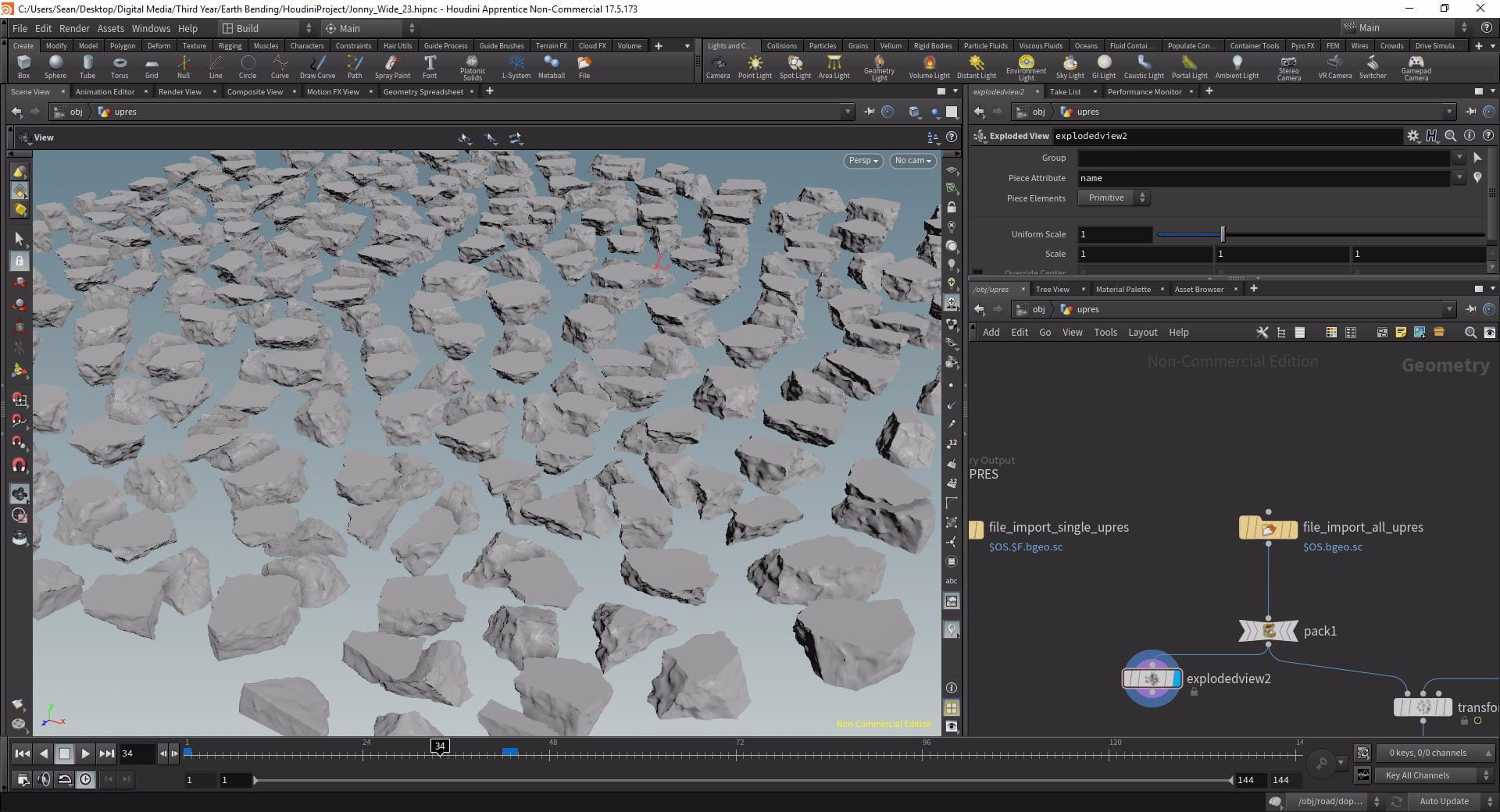
We now have our instanced pieces but we are currently limited to one per frame when really we need the entire geometry. To achieve this first write out the pieces using a ROP Output Driver, to make sure all the pieces are output change the frame range to 0 – nprims(“../object_merge1”)-1. This expression will take the number of pieces from the object merge that originally brought them in and then take away 1 as the packed primitives start at 0. Once written out, re-import the pieces using a File node, and connect a Timeshift with the Frame set to 1 so our frame 0 piece appears on frame 1 and is then clamped there. In order to speed up the calculation time of this process, in the File node change the Load type to Packed Disk Primitive. At the bottom of the chain connect a Copy And Transform with the Total Number set to the nprims expression we used before (without the -1).
Delayed Load Instancing
Using this technique we can bring in our instanced pieces and rebuild our geometry by changing their “unexpanded filename”. This can be done through the use of another Attribute VOP connected below the Copy and Transform set to Run Over Primitives. Connect a Primitive Intrinsic VOP via the File input to Opinput 1 and the Prim to the Primnum but instead of the transform as the Intrinsic we want to bring in our unexpandedfilename and we want to bring it is as a string. Looking at the geometry spreadsheet, with the Intrinsics set to unexpandedfilename, you can see we are currently bringing in the same piece over and over again.
We need to modify this so we are bringing in all our instanced pieces. To manipulate our string we first need to split it by using a Split String VOP plugged in via the String input, and the separator set to . as this is what breaks up the file names. Next we will use the Set Array Element VOP with the string plugged into the Array and a Print VOP set to Format String % with Value 1 plugged into Primnum and the output into the New Value of the Set Element Array. The Index defines which . we will split the file name at so connect a Constant set to Integer to the Index and then output the Set Element Array into the Strings input of a Join Strings VOP with the Separator set to .. Output this into the Value input of a Set Attribute VOP but with the Signature set to String Attribute, the Attribute Class set to Primitive Intrinsic and the Attribute set to unexpandedfilename. Plug i1 into the Primnum import and you will see the filename change on the geometry spreadsheet. Change the constant value between 0 and 3 until your file name reads correct (it should be the format as before but instead of bringing in the same frame it is bringing in each of the instanced pieces).
Applying the simulation data
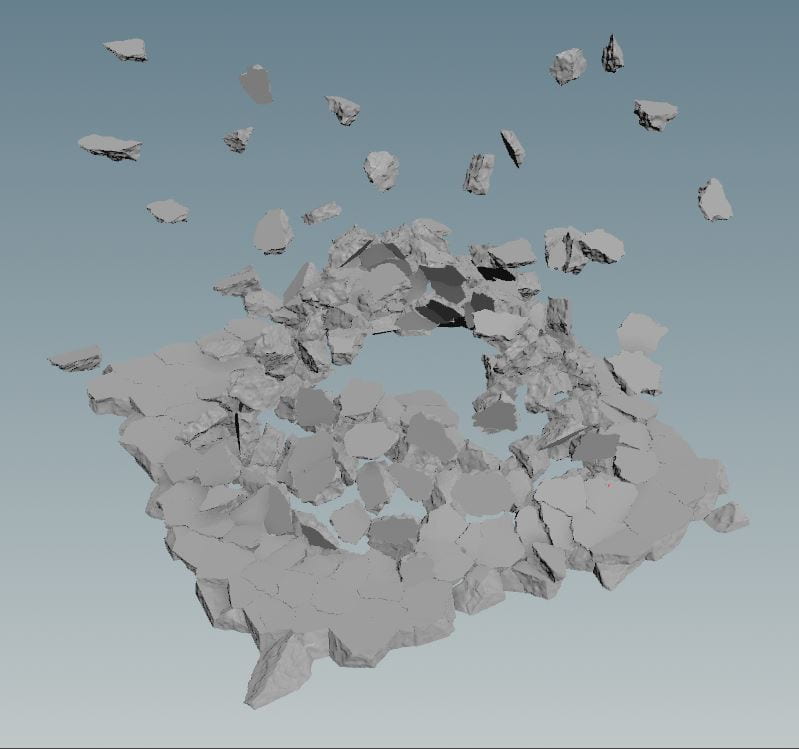
Back at SOPs level you should now have a bounding box for every instanced piece that build up to make the original geometry however we need to apply our simulated movement using a DOP Import. Set the DOP Network to the correct simulation and the Object Mask to rbdOuter making sure the Import Style is set to Create Points To Represent Objects. This will bring in the simulation data but only as a single point for each fractured piece. Write this node out using another ROP Output Driver and then reimport it with a File. We will stick our instanced pieces to these points using a Transform Pieces SOP, plug the pieces into input 1 and the points into input 2.
Drop a Null at the end of the chain set to an appropriate name and the process is complete. This same procedure can be copy and pasted if you require it again and the outputs can be merged together. Even though in the viewport you cannot see the pieces, when it comes to rendering this will change and it will be rendered like any other piece of geometry, the benefit of using bounding boxes to represent the geometry is that the high resolution pieces are very resource heavy and so if you have a lot of them it will slow down your machine significantly if you bring them all in as full geometry. Therefore it is prudent to have this step be the last one you do before rendering to minimise change of error, however the limitations of this workflow is that you cannot apply a material to the entire geometry at this stage it must be done before hand, you can only apply a material to each individual piece.
Tutorial Video
In this video guide I walk through the process of UpResing fractured geometry however, because the prim count was so small I do not use the Delayed Load Instancing technique:
References
- Pluralsight (2018) Architectural Destruction in Houdini. Available from: https://app.pluralsight.com/library/courses/houdini-architectural-destruction [accessed 31st March 2019].