
Now I have a firm understanding of fracturing in Houdini the next step in improving my fractures is using constraint networks. Invisible geometry that can be used to hold geometry together, bind it to one point and make its inter-piece bonds stronger.
A Basic Glue Network
Setting up the network
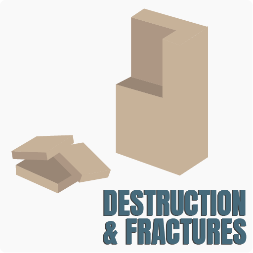
Setting up another basic fracture of a cube as I explained in the Voronoi and Boolean post one can set up a very quick, basic, constraint network. To create a constraints first make sure your Assemble node is transferring the name attribute then connect it to a Connect Adjacent Pieces SOP. In this situation the geometry is pieces and we want it to be connected via points so the default Connection Type is fine, however if nothing is showing up in the viewer it is because the points are too far apart – this can be fixed by increasing the Search Radius. The default Max Connections of 1 is also too low, currently a point is only making one connection meaning the geometry will still not stay together, we want a network not a few lines but by increasing the Max Connections to somewhere between 4 and 8 this can be rectified creating a web of lines between the pieces.
At the moment this is still not a constraint network however as it won’t actually hold the geometry together, the lines are just lines until an attribute is applied so the next step is to connect a Primitive Wrangle to the bottom of the chain. To apply the necessary attributes the following VEXpression is required:
s@constraint_name = “glue”;
s@constraint_type = “all”;
Broken down this means:
- s = We want to create a string and to do that this is required.
- @constraint_name/type = the attributes required to create are the name of the constraint and what kind of constraint it can be.
- = “glue” = the name of the constraint name in this case is glue but it can be anything, it is what will be referenced in DOPs.
- = “all” = Which constraint types can be adopted by the network.
Applying the network in DOPs
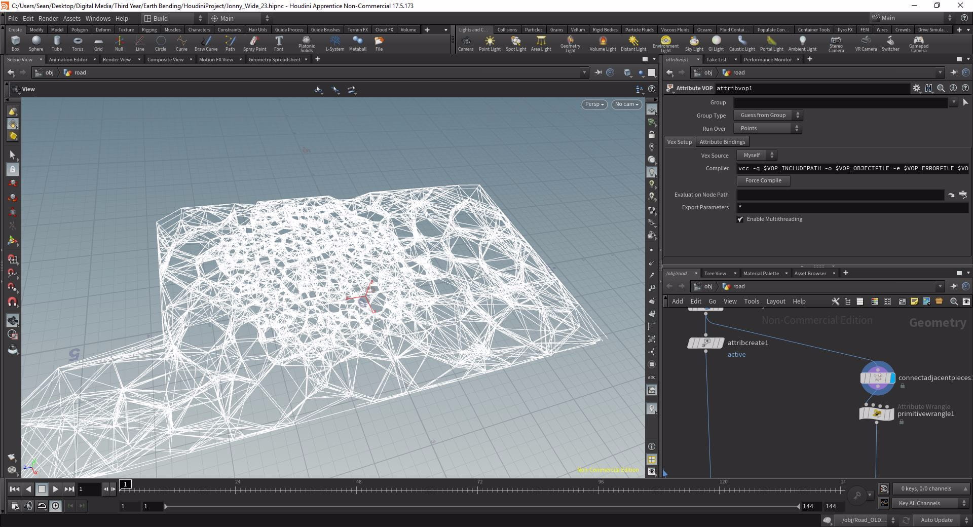
With the network set up it can now be taken into DOPs. Firstly set up a DOP Network as before in the Voronoi section with the Assemble plugged into input 1 and this time with the constraint network plugged into input 2 and the Object field set to rbd*. Once the network has been set up to fracture the geometry as normal drop a Constraint Network below the solver. At first this will provide an error but that is just because it needs more information. Firstly it needs to know where the constraint network is, we plugged into the second input so put the following expression in ` backticks:
opinputpath("..", 1)
All this does is points the path at whatever is plugged into the second input. The error is still there however as the network still needs a constraint relationship. As this will be a glue constraint drop down a Glue Constraint Relationship and connect it to the second input of the Constraint Network. As we set the constraint_type to “all” the network can be used as a glue network however to actually use the correct attributes from the Primitive Wrangle the field in the Data Name needs to match the constraint_name which, in this case, was “glue”.
Now we have an effective constraint network and if we play our simulation, instead of completely shattering, when the geometry hits the ground only the pieces that actually collide with the ground plane are broken off. To modify the power of the glue network so it is either stronger or weaker you can change the Strength parameter of the Glue Constraint Relationship.
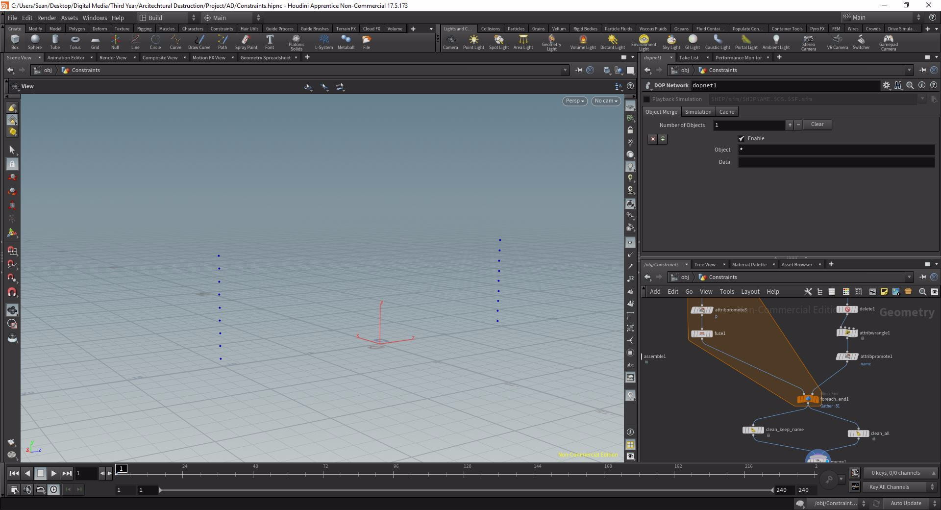
A constraint network from scratch
Initial geometry is not required to make a constraint network, you can build it from anything and then apply it to other geometry afterwards. To do this with a single point drop an Add node creating a single point at the origin and then place it wherever you want using a Translate. To connect the fractured geometry we cannot use the Connect Adjacent Pieces as our point is not a part of the geometry so instead drop down a For Each Named Primitive loop with the Assemble of the fractured geometry connected to the second input of the end. Firstly we need to merge our point into the loop, then below the merge connect another Add set to Delete Geometry But Keep Points; this will delete the fractured geometry but keep a point for the centre of each piece. Then, to connect these fracture piece points to the original point drop another Add and in the Polygons > By Pattern set the Polygon 0 field to *. Now if you view the end of the For Each loop you can see our constraint lines binding all the fracture pieces to the original point.
Again we need a primitive wrangle with the same lines of VEX as before, this time name it whatever you want just remember it so you can reference it back in DOPs later – I used “con”. If you duplicate the DOP Network from before but change the inputs so the second one is our new constraint network then dive in we can set the new constraint relationship up in a couple of steps. This time, instead of a Glue Constraint Relationship use a Spring Constraint Relationship and set the Data Name to the corresponding constrain_name, in my case “con”. With the default values it will have very little effect but if you increase the strength to something like 1000 then when pieces fall they will be held up by invisible pieces of rope or elastic. It is worth noting that because we have been using constraint_type = “all” that with both networks we can use any kind of constraint relationship and as long as the correct constraint_name is used then the network will be applied. Also, if you want to anchor the initial point to a piece of fractured geometry it can be done so using the name attribute.
Using Multiple Constraints at once
Creating New Inital Geometry
You do not have to use only one set of constraints for your fractured geometry however, you can use multiple. To demonstrate this create a new Geometry network with a Grid on the XY plane set to 20 x 6 and the centre y value to 3. Firstly to disconnect this geometry use a Resample with Maximum Segment Length disabled. Using a Poly Extrude turn the grid into blocks using a distance of about 0.7 and Output Back enabled. Houdini needs to know that the blocks are separate pieces of geometry so use a Connectivity node to create the class attribute on primitives. We also want to name our pieces based on this class value so drop an Attribute Wrangle at the bottom of the chain set to Run Over primitives. To apply the name attribute use the following VEXpression:
@name = “piece_” + itoa(i@class);
Broken down this means:
- @name = the attribute we want to create.
- “piece_” = What the name attribute will actually be and we want it to be piece followed by a number hence the underscore.
- (i@class) = Our class value is an integer so it is i@.
- itoa = This function converts an integer (which our class currently is) to a string (which we need for our name attribute).
- + = we want the number after “piece_” to correspond to the class attribute so we will add it.
Now, if you view the Geometry Spreadsheet you can see our name attribute has been created and it corresponds to the relevant class attribute so when class = 4, the name = piece_4.
To test whether this is working drop down an Assemble with the Output Prefix set to “piece_” and Create Packed Geometry and Cusp Edges enabled as well as a DOP Network set up as we have done before. In the packed object give the blocks a little angular velocity and they should all spin out wildly, as long as the pieces aren’t connected things are fine – make sure to remove the angular velocity after though, that’s just for testing. Instead we will use an animated Sphere, drop one down in the Geometry network and animate it using a Transform so it moves through the wall over a period of a second. Connect it to the second input of the DOP Network and, inside the network, drop down a Static Object and merge it with the Ground Plane. Point it at the second input using the opinputpath expression, enable Use Deforming Geometry so it animates and then play the timeline, the sphere should break the wall apart.
Creating points for the web
Back on the geometry level we are going to create two constraints that will hold the wall together. We need the “class” and the “name” attribute created by the attribute wrangle so the second chain should branch off from below that. Enable Output Side on the PolyExtrude so the group “side” is enabled then isolated the extrudeSide pieces using a blast node. Create some primitive normals with a Normal node and then, using a Delete node set to Delete By Range delete the horizontal side pieces. In the viewport select all the pieces but the very side pieces and press delete to blast them away and we have our isolated side pieces.

Dropping down another For Each Loop connect the second input of the end of the loop to the Blast node and then between that connection drop an Attribute Promote. Using this we will transfer the name attribute from primitives to points, in the For Each Loop we need to update the paths now so change the Piece Attribute to class. We don’t want the primitives only the points so within the loop drop an Add node with Delete The Geometry But Keep The Points enabled but really we want a single point per primitive in the face’s centre. To do this we will use two Attribute Promotes: in the first one, below the add, we want to promote “P” (the position) from Points to Detail and then on the second one invert this. This has actually just stacked our points on top of each other whereas we need a single point so use a Fuse node to merge the 4 points into 1 with Keep Unused Points enabled and Remove Degenerate disabled.
creating the constraints
Now we have our side points we need to create two branches so we have enough points for our constraint web. Create these branches using two Clean nodes Remove Degenerate Primitives and Unused Points disabled on each. Make sure Remove Attributes is enabled on both but on one set the field to * ^name – this will keep the name attribute. Merge these two back together and drop a Connect Adjacent Pieces as before to create the constraint web. To prepare the constraint network for DOPs drop a Primitive Wrangle with out familiar VEX lines:
s@constraint_name = “hard_constraint”;
s@constraint_type = “position”;
This will be our “hard constraint”, I.E. the tougher of the two constraints to break and it is the position that we want to constrain hence the new fields. Plug this into the third input of the DOP Network and jump into the simulation and set up the constraint network pointed at the third context geometry. This is a hard constraint so use a Hard Constraint Relationship DOP updating the Data Name to hard_constraint. Reduce the Rest Length to 0 and if you play the simulation you can see the edge bricks are clamped to the constraint points.
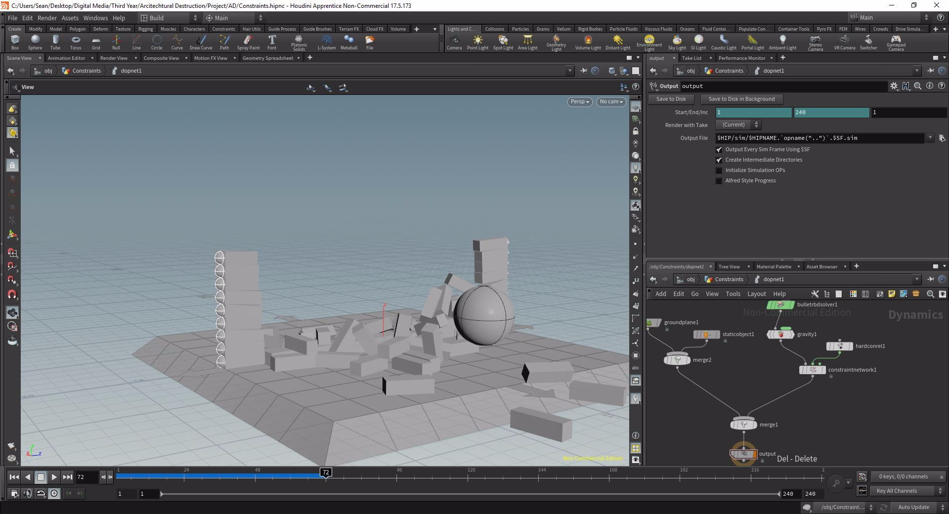
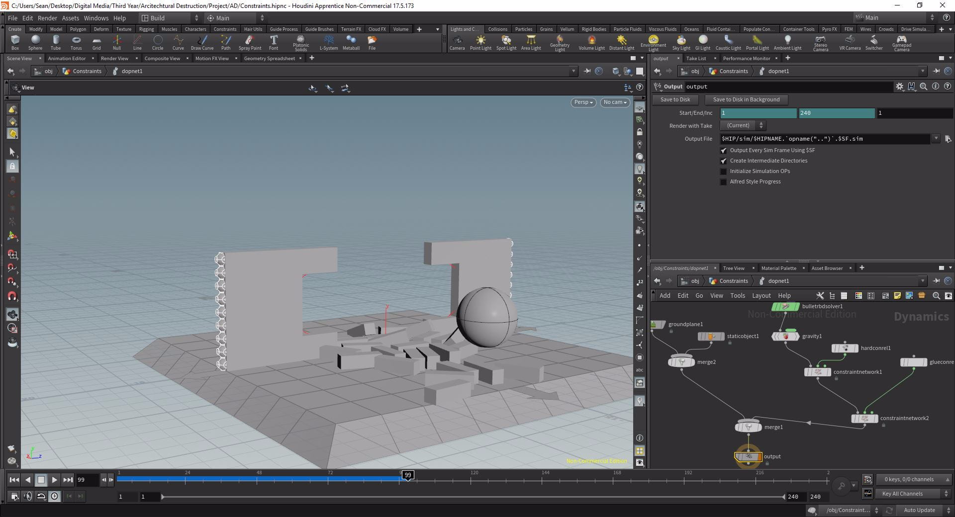
Now we will add a glue constraint to keep the bricks together. Back at SOP level we need to duplicate some nodes to create our glue constraint. Highlight the Attribute Promote and the For Each Loop and duplicate it, this time with the Promote input plug into the output of the Attribute Wrangle in the original chain. Now we have one point for each of our blocks and we can create a glue constraint network as we did in the earlier section but this time with the Connect Type set to Adjacent Points. Plug the output of the Primitive Wrangle into the 4th input of the DOP Network and jump in.
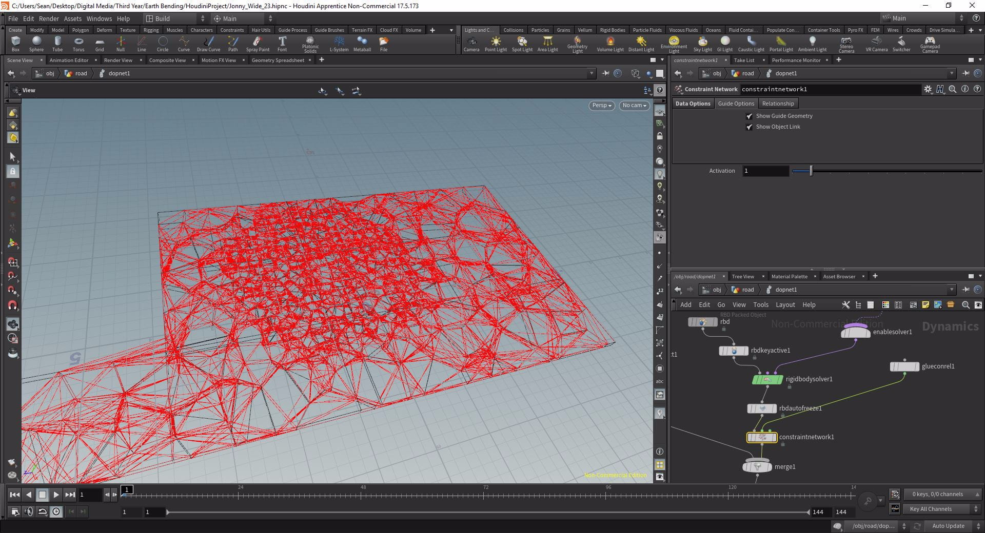
Create another Constraint Network DOP with the path pointed at opinput 3 and with a Glue Constraint Relationship with the Data Name set appropriately. If we increase the strength to something like 150000. If we play the timeline now only some of the pieces are blasted away rather than the entire wall and the wall stays upright rather than toppling forwards thanks to the combination of our two constraint networks.
Conclusion
Here we can see the value of constraint networks. Initially when we create a Voronoi fracture or any other kind of fracture in Houdini and then simulate, the pieces are already broken and are just starting the simulation next to each other. With constraint networks however we can re-attach our geometry but in a way that can be broken at will and most importantly in a realistic way. This process will come in very useful when creating my own fractures and I will likely use a combination of networks in my sims.
Tutorial Video
Towards the end of this video I walk through the process of creating a Glue Constraint Network and setting Active Values to limit piece interactions:
References
- Pluralsight (2018) Architectural Destruction in Houdini. Available from: https://app.pluralsight.com/library/courses/houdini-architectural-destruction [accessed 18th March 2019].