Currently I have only been looking at Houdini as a program in of itself and not used it in tandem with other programs better optimised for certain functions. In industry Houdini is primarily used for FX work whereas modelling would be done in Maya and compositing and matchmove in Nuke. For this semester’s project I want to start integrating my FX work with live action footage and to do this I will need to matchmove my footage. I already have some experience matchmoving in Adobe After Effects and Blender however the industry standard for this process is Foundry’s Nuke which, luckily, is available free for a year for students. My goal is to be able to take a piece of footage into Nuke, prep it for Houdini, use Houdini to add FX, then take this back into Nuke and composite a final shot.
Removing Lens Distortion
After working with Blender and Houdini extensively already I am quite familiar with the node based set up in VFX programs and so was pleased to see a similar set up upon opening up NukeX. On the left is a viewer panel, below it the node viewer and a properties window on the right similar to Houdini, there are also toolbars around the edges of the screen. All in all a very familiar set up.
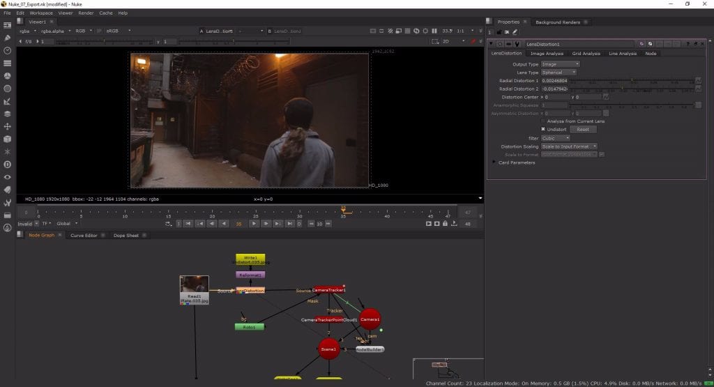
Firstly to import my footage I used a Read node and brought in the alleyway footage I downloaded courtesy of Pluralsight and plugged it into the first input of my Viewer. The footage was shot on a Canon 5D Mk. II using a 24mm zoom lens causing barrel distortion around the edges. Before I could matchmove the footage or bring it into Houdini to add FX I first had to undistort the footage or the perfect straight lines of the FX I add will not fit with the slightly curved edges of the actual footage. There are a few different methods that can be used to remove this lens distortion but after a bit of looking around online people seemed to recommend “line analysis” as the best method. This works by drawing lines along edges you know to be straight in the real world but have a slight curvature in your footage.
To do line analysis in Nuke I connected a Lens Distortion node to my Read, went to the Line Analysis tab and enabled Drawing Mode. Looking for edges to analyse I settled on the ledge above the door on the right, the frame of the stairway and some of the ventilation system. The optimal place to analyse lines is around the edge of the frame as this is where the distortion is most prominent. After settling on my final choice of lines I clicked Analyse Lines and Nuke calculated the distortion of the footage and undistorted it by stretching the edges slightly. Even though my viewer was still set to 1920×1080, the footage had now been stretched past that creating “overscan” which is something I will have to take into account when setting up my Houdini scene.
MATCHMOVING
Rotoscoping
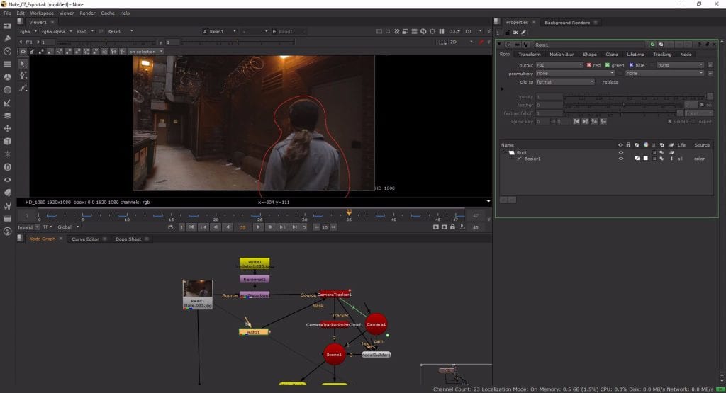
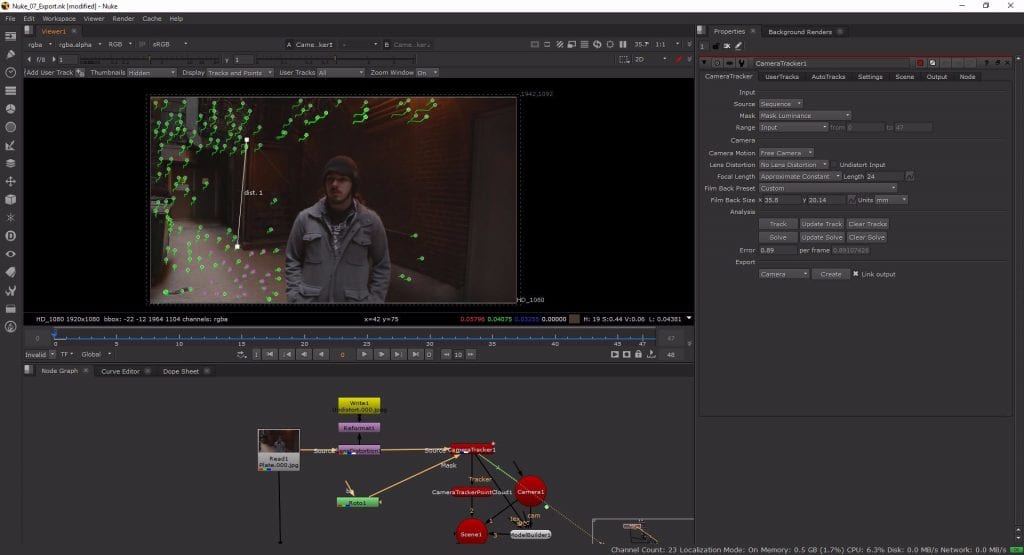
Next I connected a Camera Tracker node after the Lens Distortion to create tracking points for my scene, however I need to make sure that the person moving in the shot is not tracked or it will mess up the solve so I also dropped down a Roto node. Using the Bezier button from the tool bar I then drew a rough outline around the actor and keyframed it throughout my timeline so he is rotoscoped consistently. Then, to apply the rotoscope, I plugged the mask input of the Camera Tracker into the Roto node and set the Output to rgb.
Tracking
To set up the Camera Tracker node itself only a few parameters need to be changed. I wanted to track my sequence over its entire range so the input settings are fine already, the default camera motion is Free Camera which again fits this shot fine and as I already undistorted the shot the Lens Distortion can be set to none. The Focal Length however I do know as the camera details are given with the footage. Because I undistorted the footage the focal length may now vary never so slightly so I set it to Approximate Constant with a length of 24. As I said the camera used was a Canon 5D Mk. II so I also set the Film Back Preset to the corresponding camera which set my sensor size for me. Lastly I set my Mask to Mask Luminance meaning all the RGB data from the Roto node will be omitted, masking out the actor. I was then ready to track and clicked the Track button on the Camera Tracker node.
Refining the track
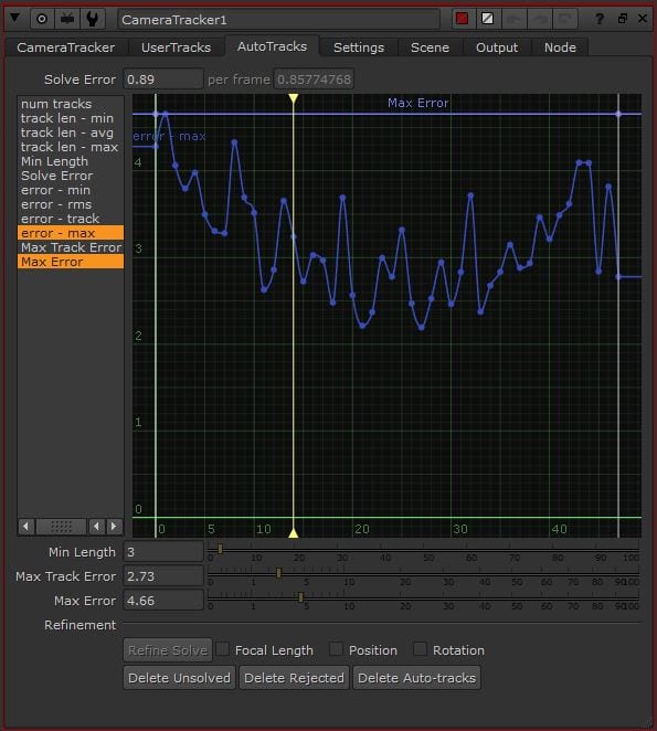
Now with all my tracking points the next step was to solve. This started me off with an error rating of 1.01 – not bad, but not amazing either. Conveniently Nuke colours tracking points based on their error rating with green being useful, red being potentially bad and orange being so bad they weren’t even included in the solve. I deleted all the orange and red points and then attempted to lower my solve error by reducing my max error threshold which governs the maximum amount of error a tracking point is allowed to have and still be included in the solve. I settled on a value of 4.66 after a few resolves and ended up with a final average solve error of 0.89 which is more than acceptable.
Creating the Camera
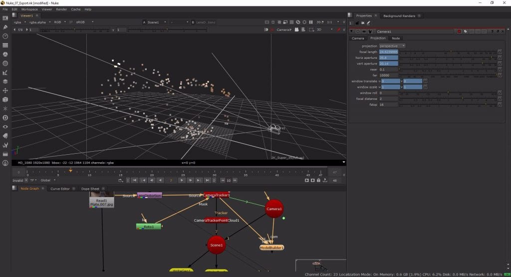
Having solved my tracking points with a significantly low error rating I nest had to prep my match moved footage to be used in Houdini, for this I needed to create a 3D camera keyframed to move in perfect sync with the real life camera the footage was filmed on. Using the export section of the Camera Tracker node I created this camera by using the Scene export. This created 3 new nodes below my Camera Tracker: a Camera node, a Camera Tracker Point Cloud and a Scene node. Looking at the Camera node’s Projection tab I could view the camera properties my footage solved with for example a focal length of 24.624 (the slight shift caused by the undisitortion of the footage) as well as an aperture of 35.8 x 20.14.
Orienting the scene
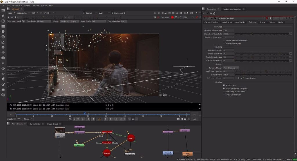
The scene has been created and I now had a ground plane and 3D camera appropriately tracked onto my scene but still floating in the air. I needed to move my ground plane to rest on the floor of the scene but before doing this I had to fix some of the points on the floor as some of them were sliding ever so slightly. This could be done in just one step by increasing the Solve Smoothness by a couple of hundredths in the Camera Tracker and resolving.
Now with a fully refined solve I had to set the ground plane, origin and scale so everything would be the correct size when I move between programs. To set the ground plane I viewed my Camera Tracker node and selected all the tracking points I was 100% certain were the floor of the alley and not just bits of slightly elevated debris. With these points selected I RMB clicked and navigated to Ground Plane > Set to Selected – this moved my ground plane down to the same level as the floor. To set the origin I selected just one of these points in the general area I would be placing my digital assets and did RMB > Ground Plane > Set Origin. Then, to make my Z (depth) axis line up with the scene I rotated the camera in the Camera Tracker node. Lastly for scale it was slightly more difficult as I did not take the footage myself and therefore have no reference for the scale, however the tutor form the tutorial gave this information so I selected two points at the top and bottom of the stair frame and using RMB > Scene > Add Scale Distance I set the distance to 152cm. Now with an accurate ground plane and scene scale all the parameters are set up so that the scene will obey real world physics and lighting operations when I move it to Houdini.
Creating Scene Geometry
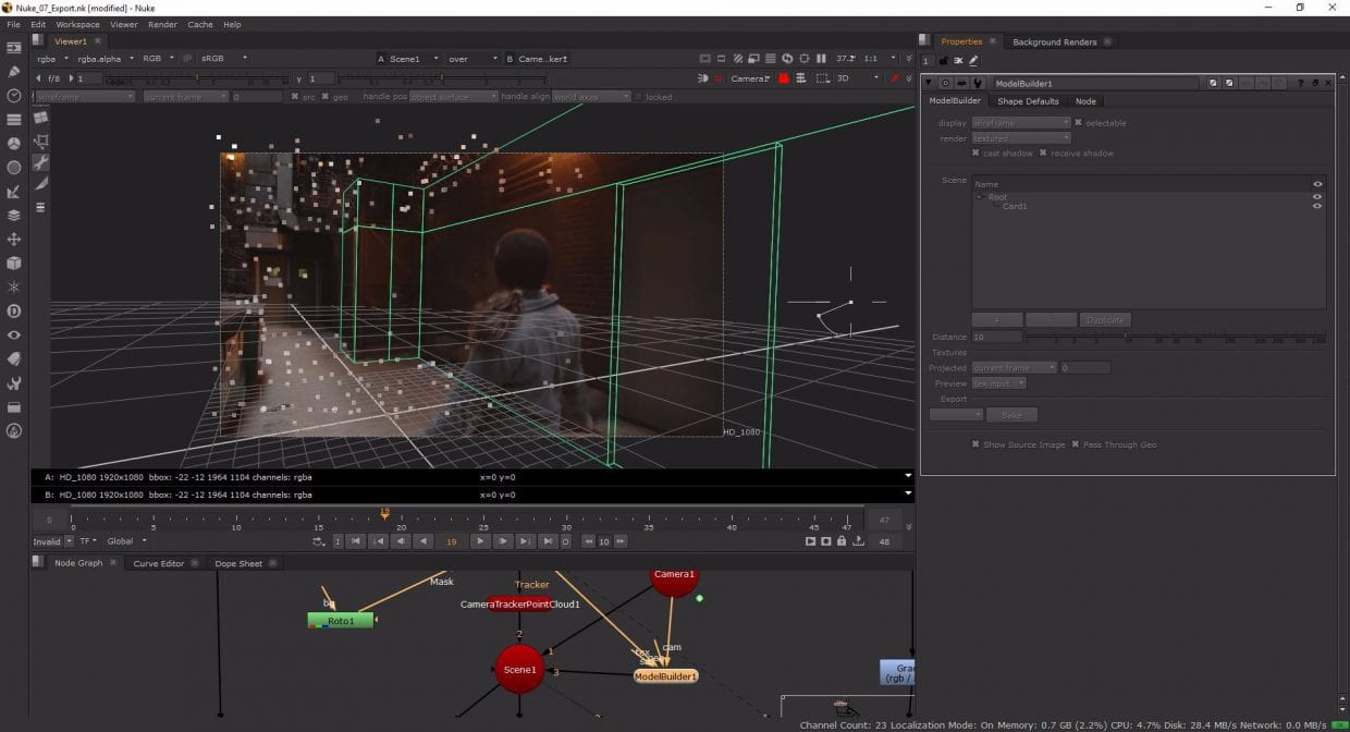
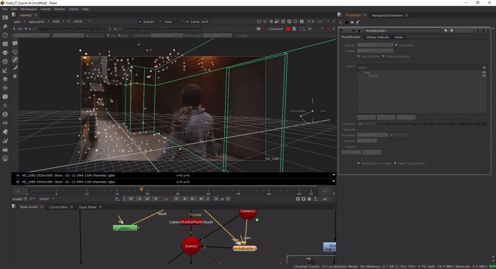
I want my 3D digital assets to cast shadows onto the geometry in the footage to increase the sense of realism so to do that I need to create shadow catchers. The ground plane is essentially flat so can be done easily using a plane in Houdini, but the wall needs to be built within Nuke to get the most accurate geometry. To do this I created a Model Builder node with the Source input set to the Camera Tracker, the Camera input set to the Camera node and the output connected to the Scene node. In this context, this node allows you to place points or geometry in the scene on the footage and have it move with the footage a bit like tracking points.
I wanted to create a shadow catcher for the right wall and stair frame in the right and centre of the frame, to do this I started with the Card Shape Default from the Model Builder node and aligned the four corners with points on the stair frame with high contrast. I scrubbed through the timeline to make sure they were sticking to the footage appropriately and realigned the points when they didn’t until I was happy with my geometry plane. Then to create the actual shadow catcher itself i first rotated the card so it was straight vertically, extended the car in the Z axis to fit the height of the frame and in the X axis to it the width then extruded the geometry down the side of the frame on the left side and up the wall all the way past the edge of the camera frame on the right. Lastly I made a few cuts and slightly extruded the a section of the wall backwards to carve out the door frame.
Exporting to Houdini
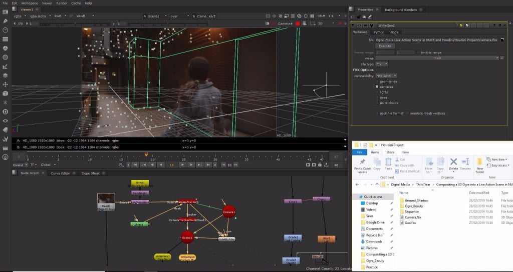
I need three exports to continue working on this footage in Houdini: the undistorted plate I created in the Lens Distortion node, the keyframed 3D camera, and the shadow catcher wall geometry. To export the undistorted plate I connected a Write node to the Lens Distortion node set to output a JPEG sequence of the undistorted footage using the file code: Undistorted.###.jpeg and then rendered it out.
I used two Write Geo nodes respectively to write out the camera and geometry as FBX files both connected to the output of the Scene node. For the shadow catcher I set the FBX type to geometry and for the camera set it to camera then hit execute and exported both files.
References
- Pluralsight (2015) Compositing a 3D Ogre into a Live Action Scene in NUKE and Houdini. Available from: https://app.pluralsight.com/library/courses/compositing-3d-ogre-into-live-action-scene-nuke-houdini-1529/table-of-contents [accessed 4th March 2019].
